Folding chair

a folding chair and folding technology, applied in the field of folding chairs, can solve the problems of not being durable or sturdy, unable to be completely folded flat to conserve, heavy to carry, difficult to fold and unfold, etc., and achieve the thinnest profile, easy to operate, and multifunctional

Inactive Publication Date: 2005-05-24
FOY MICHAEL B
View PDF11 Cites 31 Cited by
  • Summary
  • Abstract
  • Description
  • Claims
  • Application Information

AI Technical Summary

Benefits of technology

[0016]It is a general object of the present invention to provide a new and improved folding chair which is simple, inexpensive, compact, light, durable, sturdy, rigid, and multi-functional.
[0017]It is another object of the present invention to provide a folding chair which can be easily operated and can be folded or collapsed so as to ha

Problems solved by technology

Some are not durable or sturdy.
Some cannot be folded completely flat to conserve storage space, while others are heavy to carry or difficult t

Method used


Image

  • Folding chair
  • Folding chair
  • Folding chair

Examples


second embodiment

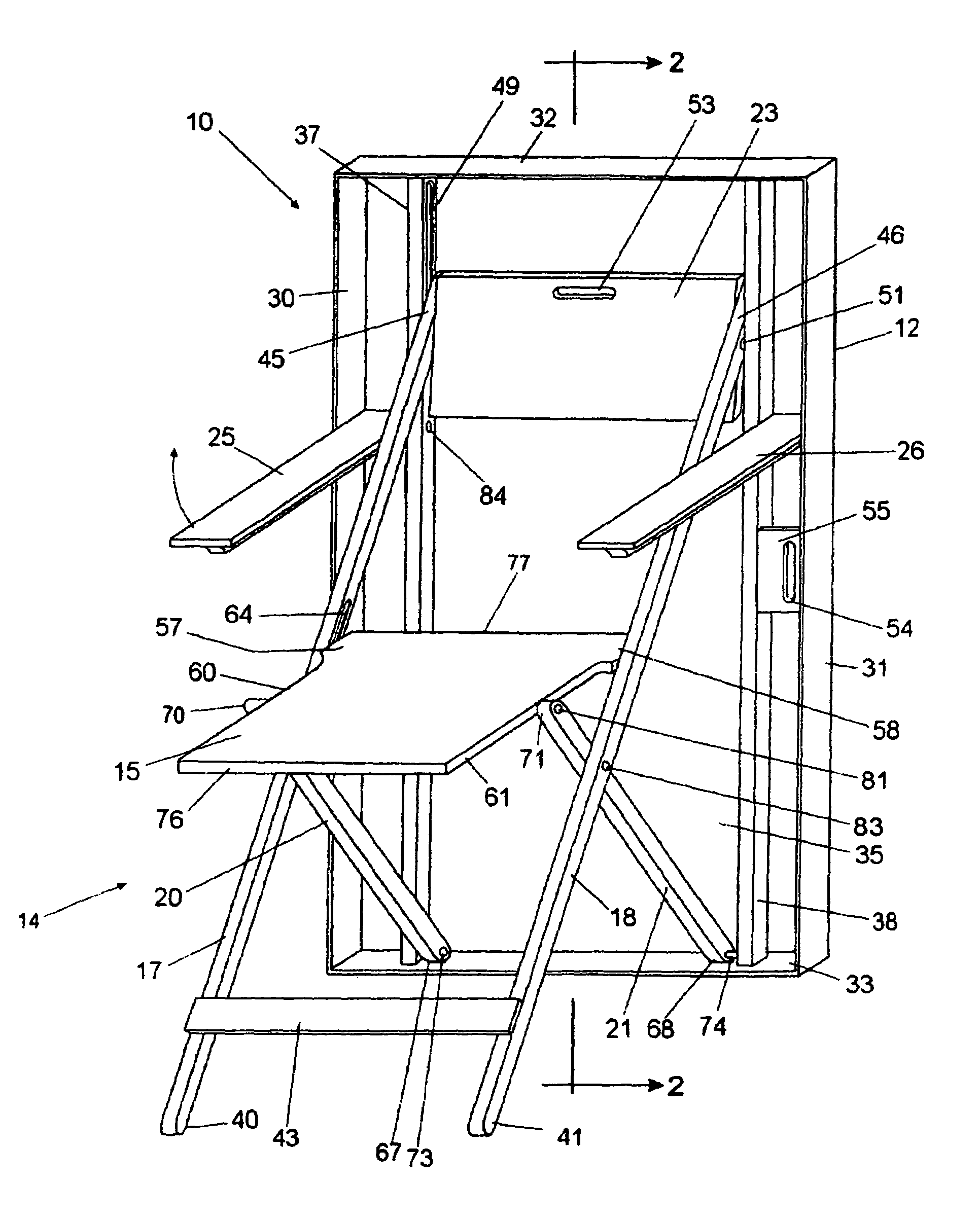
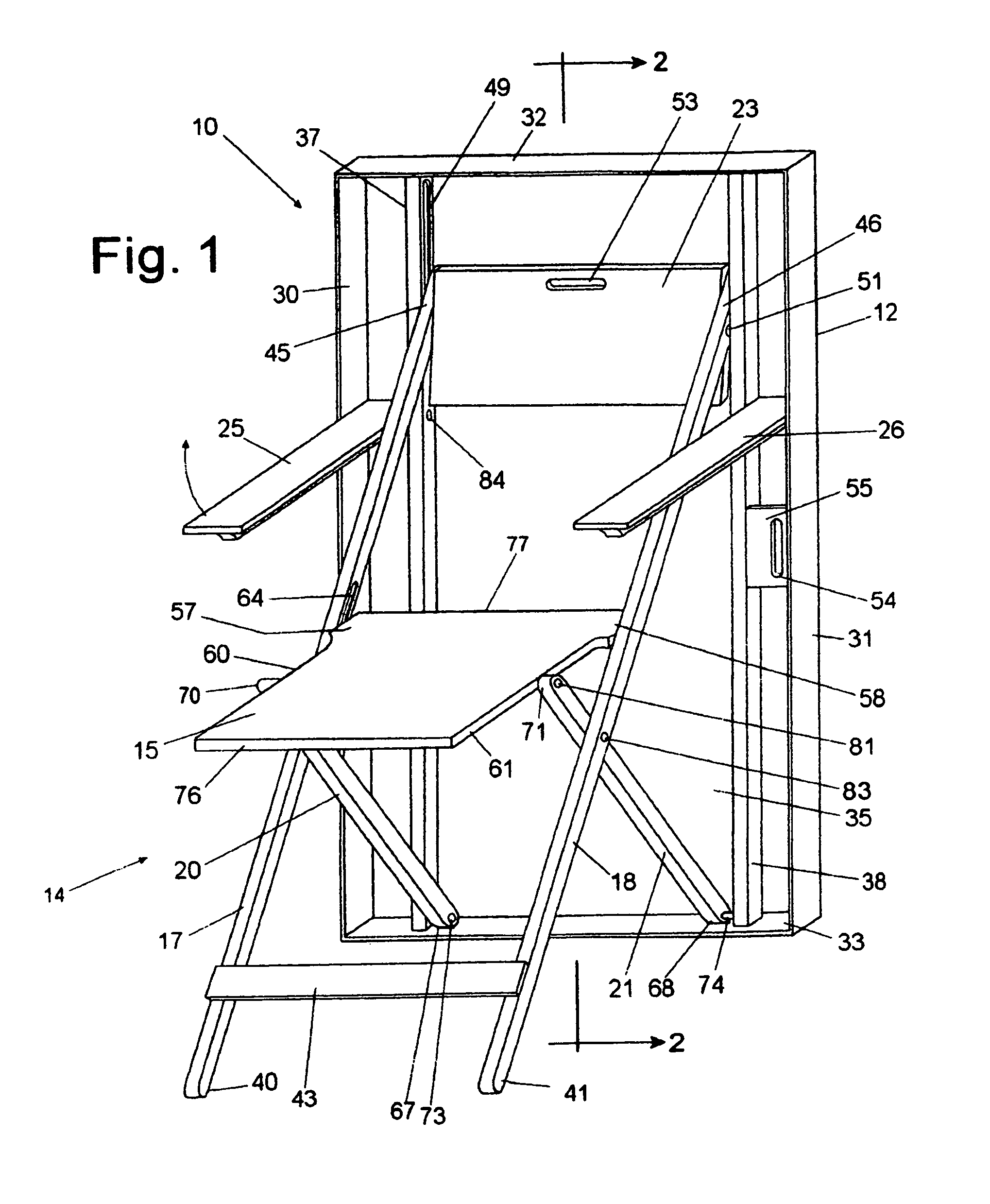
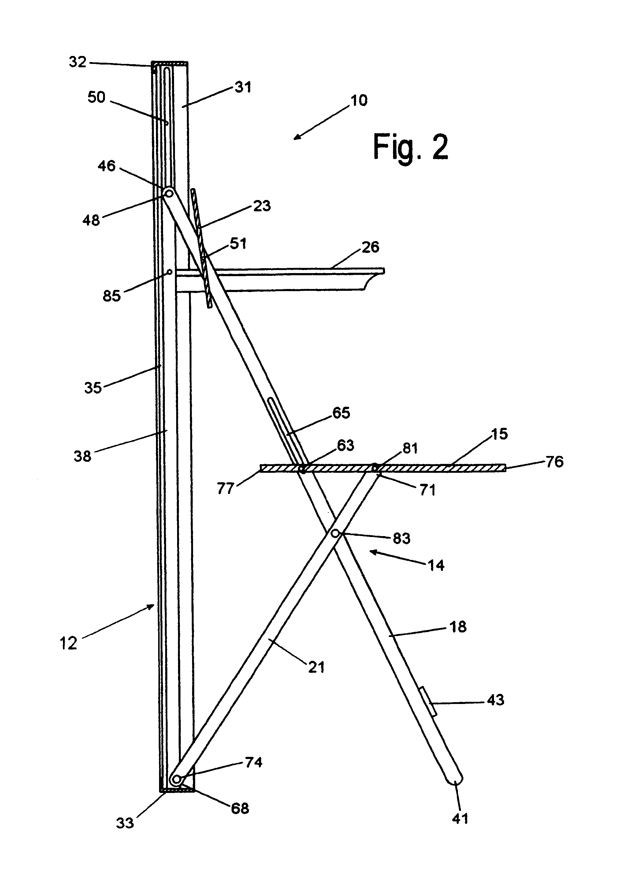
[0049]the chair and frame assembly, generally designated 110, is shown in FIGS. 6 and 7 and is seen to generally comprise three basic components: a thin, rectangular frame, generally designated 112; a folding chair, generally designated 114, including a seat 115, a first pair of spaced apart, relatively long, front legs 117 and 118, a second pair of spaced apart, relatively short, rear legs 120 and 121, and a back 123; and, a pair of arm rests 125 and 126.

[0050]The rectangular frame 112 is seen to include opposed, spaced upright thin outer side walls 130 and 131, opposed, spaced thin top and bottom walls 132 and 133 extending between the corresponding upper and lower ends of the outer side walls 130 and 131, and a back panel 135. The L-shaped walls 130, 131, 132 and 133 and the back panel 135 mounted on the inwardly extending legs of the L-shaped walls define a relatively thin, rectangular box, or picture frame, with a shallow internal cavity and an open front. Spaced inwardly from ...

third embodiment

[0056]the chair and frame assembly, generally designated 210, is shown in FIGS. 8 and 9 and is seen to generally comprise three basic components: a thin, rectangular frame, generally designated 212; a folding chair, generally designated 214, including a seat 215, a first pair of spaced apart, relatively long, front legs 217 and 218, a second pair of spaced apart, relatively short, rear legs 220 and 221, and a back 223; and, a pair of arm rests 225 and 226.

[0057]The rectangular frame 212 is seen to include opposed, spaced upright thin outer side walls 230 and 231, opposed, spaced thin top and bottom walls 232 and 233 extending between the corresponding upper and lower ends of the outer side walls 230 and 231, and a back panel 235. The L-shaped walls 230, 231, 232 and 233 and the back panel 235 mounted on the inwardly extending legs of the L-shaped walls define a relatively thin, rectangular box, or picture frame, with a shallow internal cavity and an open front. Spaced inwardly from...


PUM


Abstract

A folding chair assembly includes a frame having side, top and bottom walls, first and second pairs of legs, a seat between the legs, a first pair of leg pivots connecting respective legs together, a second pair of leg pivots engaging a first pair of cooperating slots for connecting first leg upper ends to the frame, a third pair of leg pivots for connecting second leg lower ends to the frame, a first pair of seat pivots for connecting the seat to second leg upper ends, and a second pair of seat pivots rearward on the seat of the first seat pivots engaging a pair of cooperating slots for connecting the seat to the first leg pair, whereby the chair is foldable from an open position with seat and legs extended to a closed position with seat and legs aligned within the frame. Pivoting arm rests can be provided.

Description

CROSS-REFERENCE TO RELATED APPLICATIONS[0001]This application claims the benefit of Provisional Patent Application Ser. No. 60 / 397,273, filed Jul. 19, 2002.BACKGROUND OF THE INVENTION[0002]1. Technical Field[0003]This invention relates generally to a folding chair and, more particularly, to a folding chair which is concealable within a relatively thin frame.[0004]2. Background Art[0005]In the prior art, folding chairs are well-known. The following United States patents are representative of the prior art and illustrate many of the devices that have been used in the past.[0006]In Wang, U.S. Pat. No. 4,415,201, entitled “Folding Chair Having a Reversible Seat”, issued Nov. 15, 1983, a folding chair is shown with a reversible seat and having sliding grooves on the inner side of the upper legs to facilitate up and down sliding movement of the seat while folding it for storage.[0007]In Goetz, U.S. Pat. No. Des. 314,871, entitled “Foldable Chair”, issued Feb. 26, 1991, a folding chair is...

Claims


Application Information

Patent Timeline
IPC IPC(8): A47C9/06A47C9/00A47C1/126A47C4/52
CPCA47C1/126A47C9/06A47C4/52
Inventor FOY, MICHAEL B.
Owner FOY MICHAEL B
Why Eureka
Try Eureka