Modular interbody fusion implant

a technology of interbody fusion and implants, which is applied in the field of implants for use in interbody fusion, can solve the problems of nerve damage, nerve damage, nerve damage, and even paralysis, and can not provide sufficient biomechanical support to allow a full range of vertebral motion,

Inactive Publication Date: 2005-05-24
SDGI HLDG
View PDF11 Cites 65 Cited by
  • Summary
  • Abstract
  • Description
  • Claims
  • Application Information

AI Technical Summary

Benefits of technology

[0017]In still another aspect of the present invention, a method for implanting bone grafts for spinal fusion is provided. The method includes positioning a first bone graft in a first lateral portion of the disc space and positioning a second bone graft in a second lateral portion of the disc space opposite said first lateral portion. The method further includes posit

Problems solved by technology

Further, the damaged discs do not provide sufficient biomechanical support to allow a full range of vertebral motion.
The spinal discs may be displaced or damaged due to trauma, disease, or aging.
A herniated or ruptured annulus fibrosis may result in nerve damage, pain, numbness, muscle weakness, and even paralysis.
Furthermore, as a result of the normal aging process, discs may dehydrate and harden.
This hardening of the disc reduces the disc space height which in turn produces instability of the spine and decreased mobility.
In the more severe cases, the disc tissue is irreparably damaged, and the entire disc has to be removed (discectomy).
In contrast to the bone implants, artificial implants do not fully incorporated into the fusion mass.
Such incisions extending the full width of the disc space create potential problem

Method used


Image

  • Modular interbody fusion implant
  • Modular interbody fusion implant
  • Modular interbody fusion implant

Examples


first embodiment

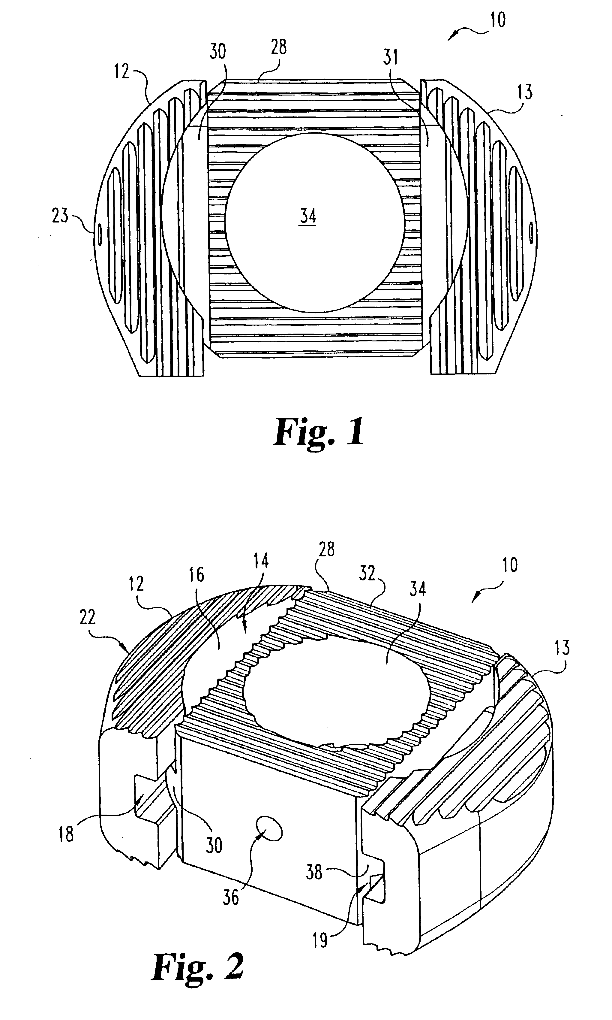
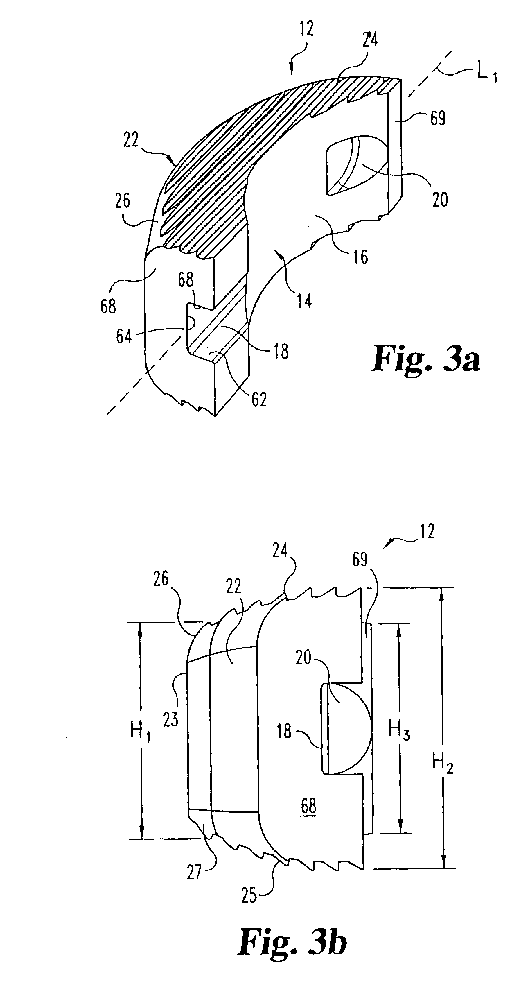
[0040]Now referring to FIG. 2, the lateral spacer 12 is coupled at its medial side 14 to the connecting member 28. It is contemplated that the lateral spacer 12 can be coupled to the connecting member 28 by using a number of different coupling mechanisms including adhesives, screws, rail / channel connections, bioresorbable fasteners and other mechanisms used to connect components as known to those skilled in the relevant art. As shown in FIG. 2, the lateral spacer 12 according to the present invention has a channel 18 that couples to rails 30 of the connecting member 28. The channel 18, as shown in FIG. 3a, is formed on the medial side 14 of the lateral spacer 12. In a preferred embodiment, channel 18 extends in substantially parallel alignment to longitudinal axis L1. Channel 18 is defined by lower surface 62, opposing upper surface 66 and intervening side surface 64. The surfaces 62, 64 and 66 are interrupted by concave medial surface 14 and resume adjacent posterior end 69. Prefer...

second embodiment

[0047]the present invention is shown in FIGS. 5-6. As shown in FIG. 5, a lateral spacer 40 has a rail 42 and not a channel. Accordingly, as shown in FIG. 6, a connecting member 44 has a pair of channels 46 instead of a pair of rails. The lateral spacer 40 and the connecting member 44 then can be coupled together by the rails 42 and channels 46.

[0048]A third embodiment of the present invention is shown in FIG. 7. A spinal spacer 48 according to the third embodiment of the present invention includes a pair of the lateral spacers 12, a first connecting member 50, and a second connecting member 52. The first and second connecting members 50, 52 are coupled to the lateral spacers 12 using the same connecting mechanisms as discussed above. Using the two smaller connecting members 50, 52 instead of a single larger connecting member 28 further reduces the required size of the original bone stock, thereby making more donor bone segments suitable for use in a modular bone graft for spinal fus...


PUM


Abstract

An interbody fusion device for engagement between vertebrae includes a pair of lateral spacers for spacing the vertebrae, and a connecting member adapted to couple together the lateral spacers when inserted between the vertebrae. The connecting member, individual lateral spacers, or the entire spinal spacer can be made of bone in order to promote fusion of the vertebrae. The modular construction permits use of bone segments otherwise unsuitable due to size or strength in stable fusion devices.

Description

REFERENCE TO RELATED APPLICATIONS[0001]The present application is a continuation patent application of U.S. patent application Ser. No. 09 / 766,948, filed Jan. 22, 2001 entitled “Modular Interbody Fusion Implant”, now U.S. Pat. No. 6,468,311 B2 which is hereby incorporated by reference in its entirety.FIELD OF THE INVENTION[0002]The present invention relates to implants for use in interbody fusion and methods of manufacturing such implants. More specifically, the present invention relates to implants formed from bone that are useful to restore height and promote bone fusion after a discectomy and methods for manufacturing such implants.BACKGROUND OF THE INVENTION[0003]One of the leading causes of lower back pain and disability results from the rupture or degeneration of one or more lumbar discs in the spine. Pain and instability are caused by compression of spinal nerve roots by protruding damaged discs into the vertebral canal. Further, the damaged discs do not provide sufficient bi...

Claims


Application Information

Patent Timeline
IPC IPC(8): A61F2/28A61F2/44A61F2/00A61F2/30A61F2/46
CPCA61F2/28A61F2/4455A61F2250/0014A61F2/4611A61F2002/2835A61F2002/30004A61F2002/30057A61F2002/30131A61F2002/30133A61F2002/30387A61F2002/30448A61F2002/30507A61F2002/30604A61F2002/30772A61F2002/30828A61F2002/30831A61F2002/30904A61F2002/4485A61F2220/0025A61F2220/005A61F2230/0013A61F2230/0015A61F2/442
Inventor BOYD, LAWRENCE M.RAY, III, EDDIE F.KOZAK, JEFFREY
Owner SDGI HLDG
Why Eureka
Try Eureka