
Multi-band helical antenna

Inactive Publication Date: 2005-05-24
ATENNA TECH
View PDF8 Cites 83 Cited by
  • Summary
  • Abstract
  • Description
  • Claims
  • Application Information

AI Technical Summary

Benefits of technology

[0011]It is, therefore, a primary object of the present invention to provide a multi-band helical antenna capable of operating in multiple frequency bands.

Problems solved by technology

The monopole antenna has a greater ability in a vertical orientation than the helical antenna, but theoretically cannot receive a signal in a horizontal orientation.
The implemented antenna structurally exhibits a single band characteristic, and is therefore unable to operate in two or more different bands.
Accordingly, the conventional antenna cannot be used in both the cellular service system and the PCS system using different frequency bands even though a matching circuit is employed thereto.

Method used


Image

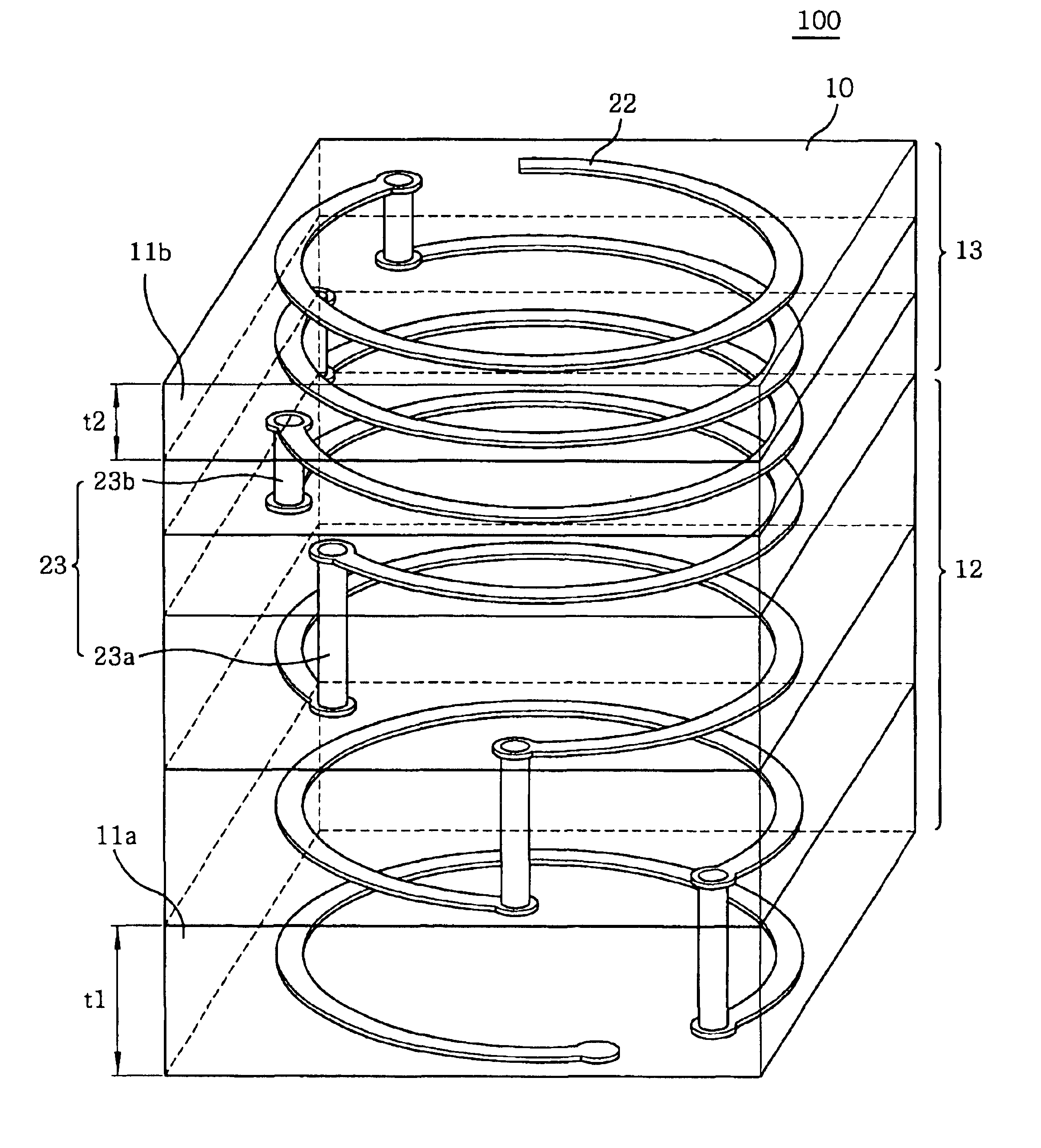
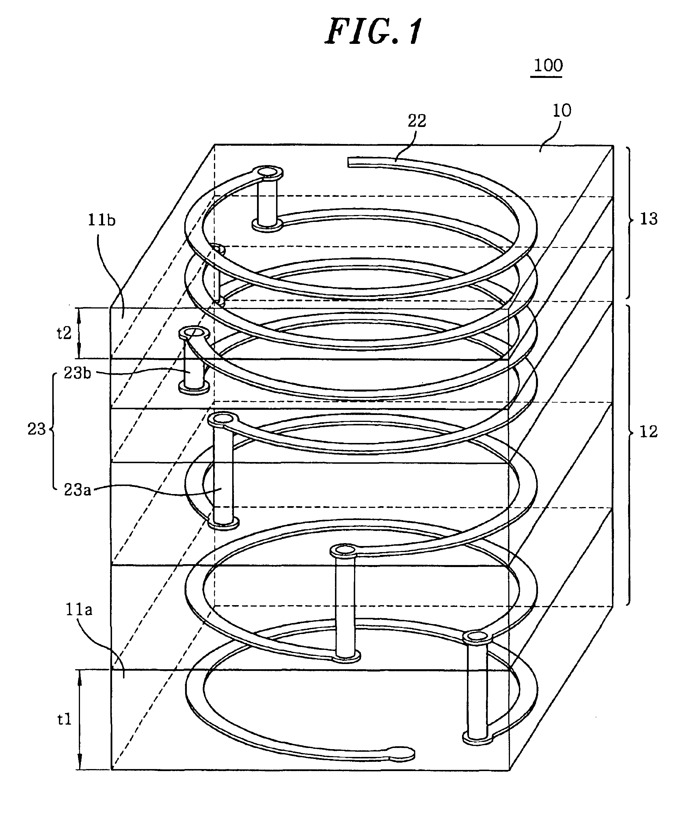
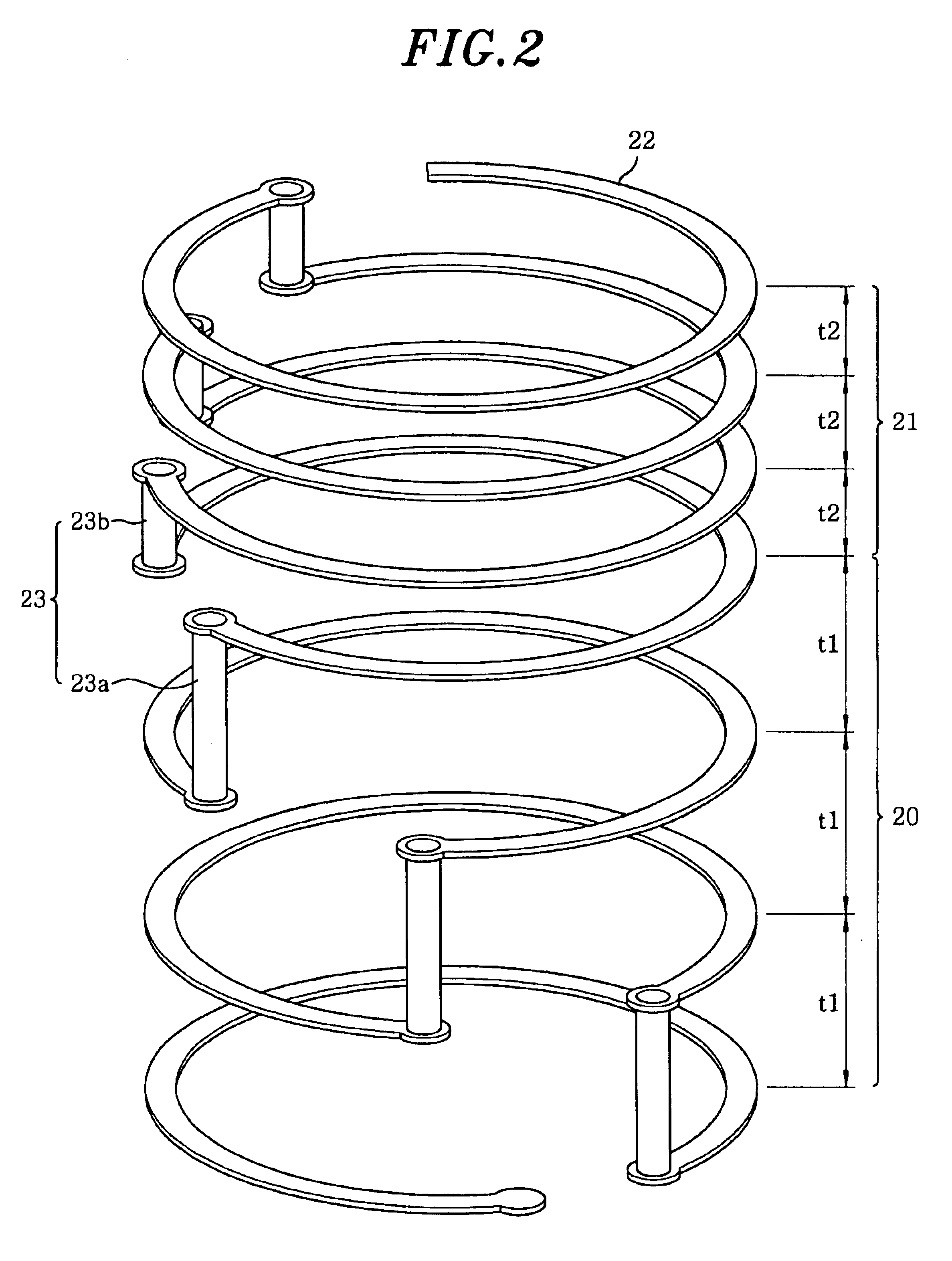
  • Multi-band helical antenna
  • Multi-band helical antenna
  • Multi-band helical antenna

Examples


second embodiment

[0053]Referring to FIG. 7, the multi-band helical antenna in accordance with the present invention includes a dielectric body 110 having a rectangular parallelepiped shape, and a first and a second metallic pattern sections 120, 121 comprising a plurality of first and second partially opened circular metallic loop patterns 122a, 122b and a plurality of first and second metallic connection elements 123a, 123b, respectively, which perform helical antenna function.

[0054]The dielectric body 110 is constructed by stacking a plurality of dielectric sheets 111 of a predetermined thickness t. The first and the second partially opened circular metallic loop patterns 122a and 122b have radii r1 and r2 different from each other, respectively. The connection elements 123a connect the adjacent loop patterns 122a and the connection elements 123b connect the adjacent loop patterns 123b. In this way, the helical antenna has a dual band resonant characteristic.

[0055]As shown in FIG. 8, in the helica...

third embodiment

[0070]In the helical antenna in accordance with the present invention, as shown in FIG. 13A, the turns in the first and the second metallic pattern sections 220, 221 are different from each other so that the helical antenna has a dual resonant characteristic and can operate in two different bands. FIG. 14 is a graph showing the dual resonant characteristic of the helical antenna in accordance with the third preferred embodiment of the present invention. Specifically, the resonant frequencies are determined by the resonant lengths of the first metallic pattern section 220 and the second metallic pattern section 221, thereby allowing the helical antenna to operate in dual bands.

[0071]In a variation of the third embodiment as shown in FIG. 13B, while the turns in the first and the second metallic pattern sections 220, 221 are the same, the entire lengths thereof are slightly different from each other. FIG. 15 is a graph showing a resonant characteristic in a wide band according to the ...


PUM


Abstract

A multi-band helical antenna of the present invention includes a dielectric body including a plurality of dielectric sheets stacked in a predetermined order and a first and a second metallic pattern sections provided in the dielectric body. The first metallic pattern includes a plurality of first partially opened metallic loop patterns and a plurality of first connection elements connecting the respective adjacent first partially opened metallic loop patterns to form a first spiral structure. The second metallic pattern section includes a plurality of second partially opened metallic loop patterns and a plurality of second connection elements connecting the respective adjacent second partially opened metallic loop patterns to form a second spiral structure. The first and the second metallic pattern sections having different entire lengths. Accordingly, the multi-band helical antenna of the present invention has a dual resonant frequency characteristic and operates in different frequency bands.

Description

FIELD OF THE INVENTION[0001]The present invention relates to an antenna for a mobile communications or radio communications terminal transmitting and receiving a radio frequency signal; and, more particularly, to a multi-band helical antenna capable of operating in multiple frequency bands by varying impedances thereof.BACKGROUND OF THE INVENTION[0002]Recently, various mobile communications systems such as a cellular service system, PCS system, GMS system and Iridium service system using a satellite are available throughout the world. For example, in Korea, cellular service, PCS and CT-2 systems are commercially provided. Portable terminals used in the mobile communications systems have been developed and pushed for improvement in compactness, multifunction, lightweight and low power-consumption. An antenna functions to transmit and receive a signal between a terminal and a base station, and is a critical component determining communication quality of the terminal. Since performance...

Claims


Application Information

Patent Timeline
IPC IPC(8): H01Q5/00H01Q1/36H01Q1/38H01Q1/24H01Q5/357
CPCH01Q1/243H01Q5/357H01Q1/38H01Q1/362
Inventor BAE, JUNG BINKIM, JONG KYULEE, JAE GUN
Owner ATENNA TECH
Learn More