Image fusion system and method

a technology of image fusion and image, applied in the field of image fusion system and method, can solve the problems of undesirable effect, unusable and unnecessary distortion, and decrease the contrast and quality of the bright image region

Inactive Publication Date: 2005-05-24
BAE SYSTEMS CONTROLS INC
View PDF12 Cites 68 Cited by
  • Summary
  • Abstract
  • Description
  • Claims
  • Application Information

AI Technical Summary

Benefits of technology

[0012]In further accordance with the present invention, contrast maps for images from a first sensor and a second sensor are combined to form an intermediate contrast map, which is then compared with a contrast map of third image to form the processed image.
[0013]In further accordance with the invention, the image fusion method and system are used in connection with directing a moving vehicle such as an aircraft, watercraft, automobile, or train.
[0014]In further accordance with the invention, the intensity or luminance of one or more image sections is adjusted across the processed image. One sensor is selected as a reference sensor, and an average intensity of regions of the reference sensor image is determined. The intensity of the same or corresponding region or an adjacent region in the processed image is adjusted by combining the determined average luminance values of the reference image and intensity values of the processed image.
[0015]Also in accordance with the invention, the method and system are implemented to filter portions of the sensor images before contrast comparisons are performed.

Problems solved by technology

First, known image fusion techniques typically result in undesirable and unnecessary distortion.
This undesirable effect is the result of incorporating elements of the blurry pixel(s) into the clear pixel(s) through addition or averaging.
As a further example, adding unnecessary background regions to a bright image region can decrease the contrast and quality of the bright image region.
For example, if regions of two images have high dominance or are bright, then adding two bright regions together can result in a final image that is “overexposed” or too bright.
These systems, however, are also deficient in that the complete image from each sensor is received before the process of constructing a pyramid can begin.
This requirement typically results in a time lag of at least one image from the slowest sensor.
Such a time lag is unacceptable in sensors placed on fast moving platforms, such as aircraft or other vehicles, or more generally where real-time operation is desired.
These techniques, however, can also be deficient in that they typically involve analyzing and assigning saliency weights to each pixel or region of the entire image.
As a result, excessive time is wasted analyzing regions of entire images and their corresponding saliency values.
These shortcomings are particularly problematic when known image systems are used in connection with time sensitive activities, e.g., landing an airplane, driving a tank, etc.
Known techniques, however, typically cannot generate quality images within these time constraints or typically do so only after full images are available for processing.

Method used


Image

  • Image fusion system and method
  • Image fusion system and method
  • Image fusion system and method

Examples


Embodiment Construction

[0031]In the following description of embodiments of the invention, reference is made to the accompanying drawings which form a part hereof, and which is shown by way of illustration specific embodiments in which the invention may be practiced. It is to be understood that other embodiments may be utilized as structural changes may be made without departing from the scope of the present invention.

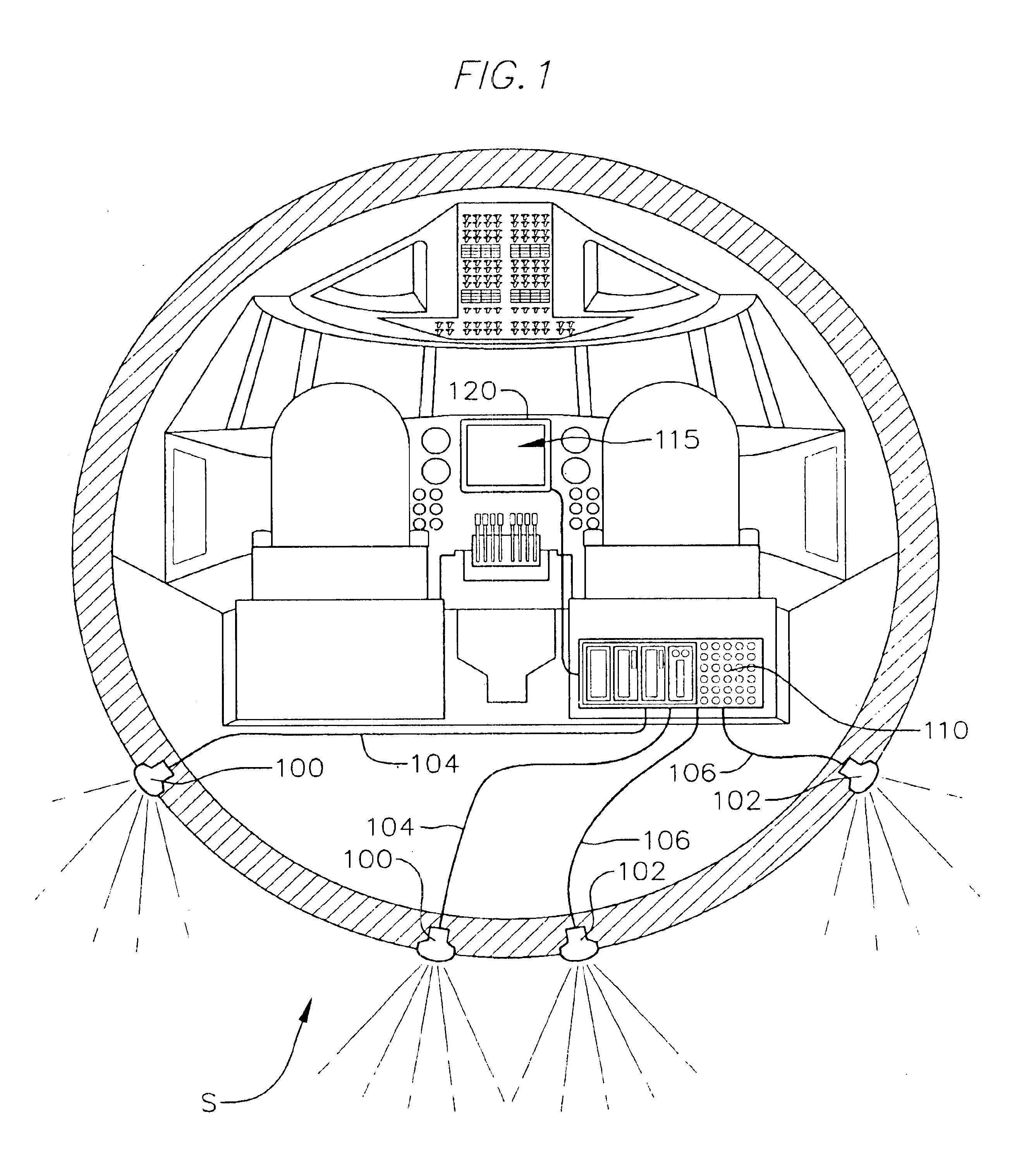
[0032]With reference to FIG. 1, a view from a cockpit in an aircraft, a system S of the present invention is shown, having sensors 100, 102 and a processor 110 and a display 120. The sensors 100, 102 provide respective image data or streams 104, 106 (i.e., sensor or source images) to the processor 110, e.g., a computer, micro-controller, or other control element or system. The sensors can detect the same, overlapping, or different wavelengths. Moreover, the sensors can also detect the same field of view, or overlapping fields of view.

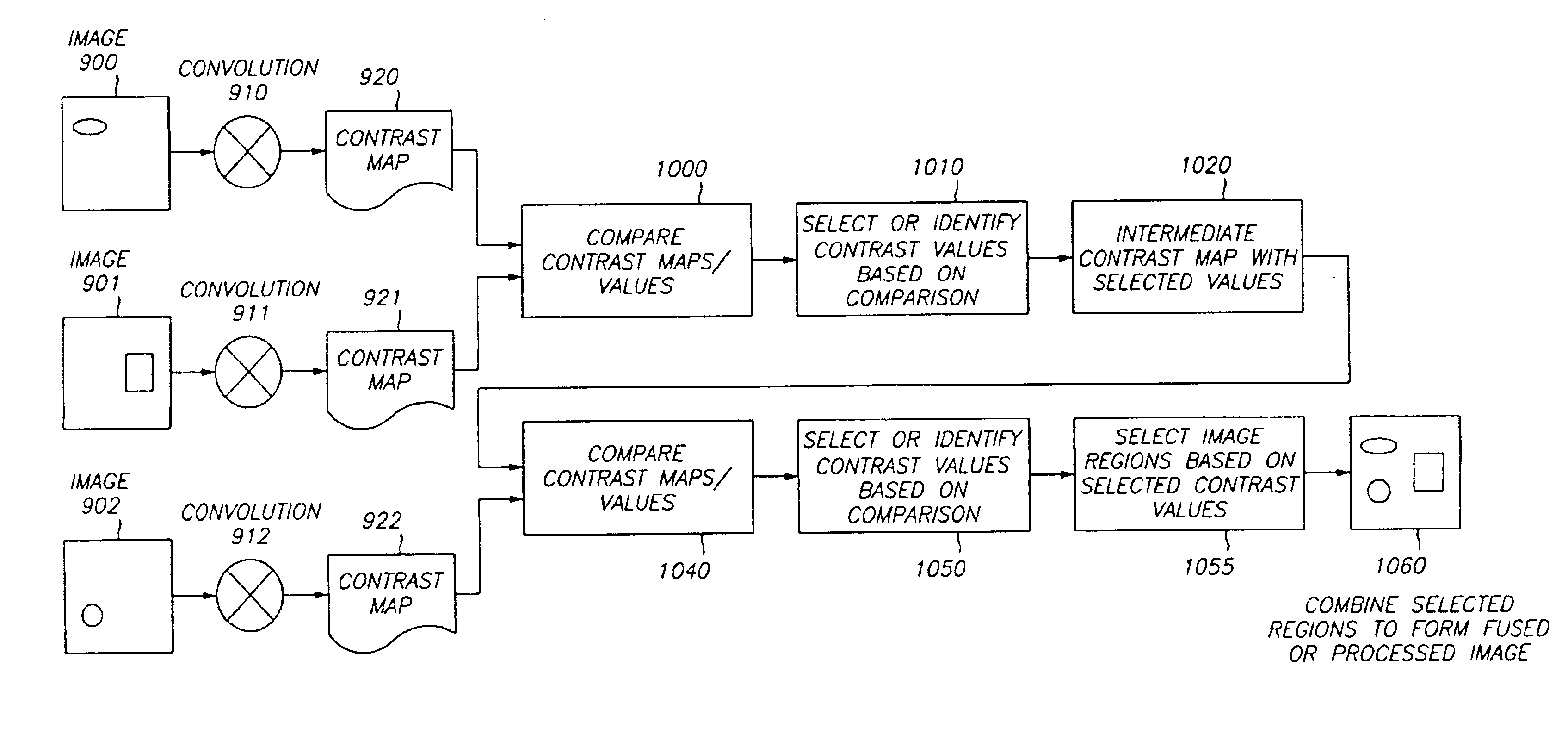
[0033]The processor 110 is programmed to selectively combi...


PUM


Abstract

A contrast-based image fusion system and method of processing multiple images to form a processed or fused image including regions selected from one or more images. Images are divided into image regions. Portions of the images are filtered if necessary. A contrast map is generated for each image via a convolution kernel resulting in a contrast map with contrast values for each image region. Contrast values are compared and image regions are selected based on a selection criteria or process such as greater or maximum contrast. The selected image regions form the fused image. If necessary, the luminance of one or more portions of the fused image is adjusted. One sensor is selected as a reference sensor, and an average intensity of each region of the reference sensor image is determined across the reference sensor image. The intensity of one or more regions in the final image is adjusted by combining the determined average luminance values and intensity values of the final image.

Description

FIELD OF THE INVENTION[0001]The present invention relates generally to imaging systems and methods, and more particularly, to an imaging system and method that selectively fuse or combine regions of images from two or more sensors to form a single, processed image.DESCRIPTION OF RELATED ART[0002]Image fusion generally refers to combining or merging portions of two or more images into a single processed image. Image fusion is commonly used when two or more detectors are used in generating an image, whereby the image displayed to a user or provided to an automated processing system is combined from information provided by each of the sensors.[0003]One manner in which known systems combine images from different sensors is by merely adding the two images together on a pixel by pixel basis. Thus, for example, for rendering a two-dimensional (2-D) processed image of pixels arranged in an n×m matrix wherein each pixel position is identified by the position (x,y), a value or data in pixel (...

Claims


Application Information

Patent Timeline
Patent Type & Authority Patents(United States)
IPC IPC(8): G06T15/50G06T5/00
CPCG06T5/50G06T15/503G06T2207/20221G06T7/20H04N5/74G06V10/20
Inventor TIANA, CARLO
Owner BAE SYSTEMS CONTROLS INC
Why Eureka
Try Eureka