
Image forming apparatus

a technology of image forming apparatus and forming tube, which is applied in the direction of electrographic process, instruments, transportation and packaging, etc., can solve problems such as detection errors in sensors

Inactive Publication Date: 2005-05-24
INTEL CORP
View PDF3 Cites 19 Cited by
  • Summary
  • Abstract
  • Description
  • Claims
  • Application Information

AI Technical Summary

Benefits of technology

[0009]It is another object of the present invention to provide an image forming apparatus having (1) stable toner density sensing, (2) recording medium detection, (3) control of a process for forming visible toner, (4) recording medium conveying control, and (5) a miniature and inexpensive configuration.

Problems solved by technology

However, that configuration uses a large space between the photosensitive body and the transfer belt to turn the photosensor and utilizes many parts to mount the photosensor rotatably.
Moreover, the transparency (or amount of obstruction) of the transfer means changes over time due to scratches from friction between the transfer means and the recording medium supported on the transfer means.
Thus, a detection error may occur in the sensor because of a change in a quantity of reflected light of the sensor.

Method used


Image

  • Image forming apparatus
  • Image forming apparatus
  • Image forming apparatus

Examples


Embodiment Construction

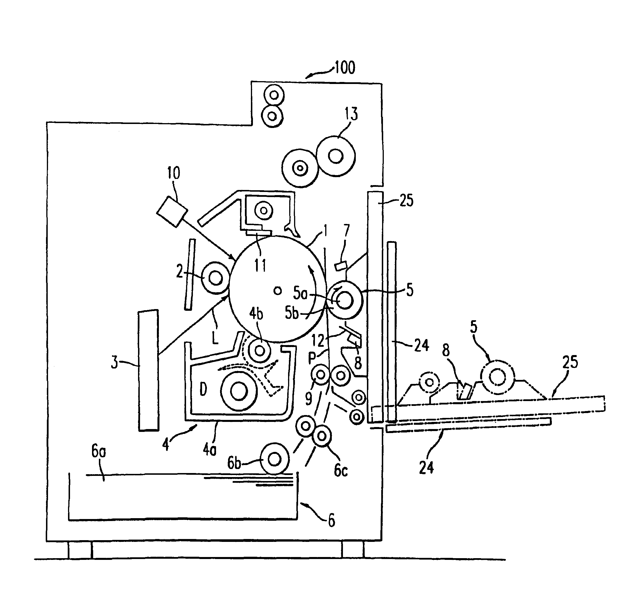
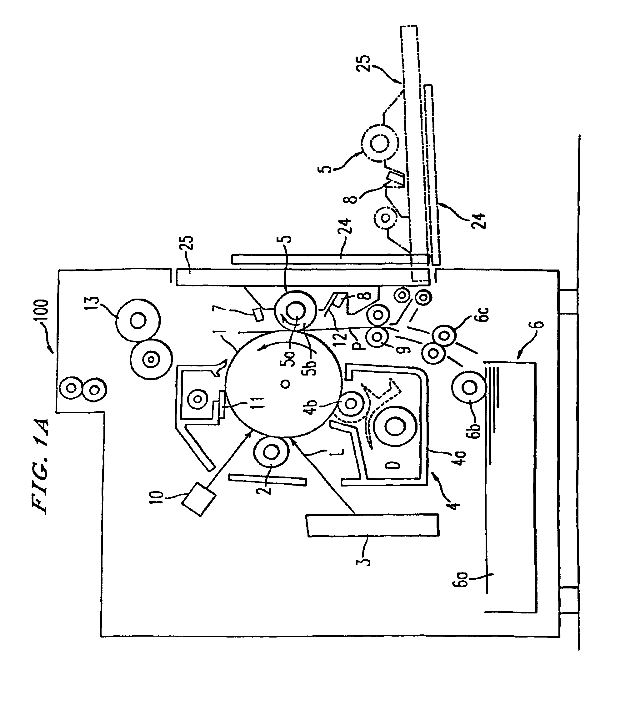
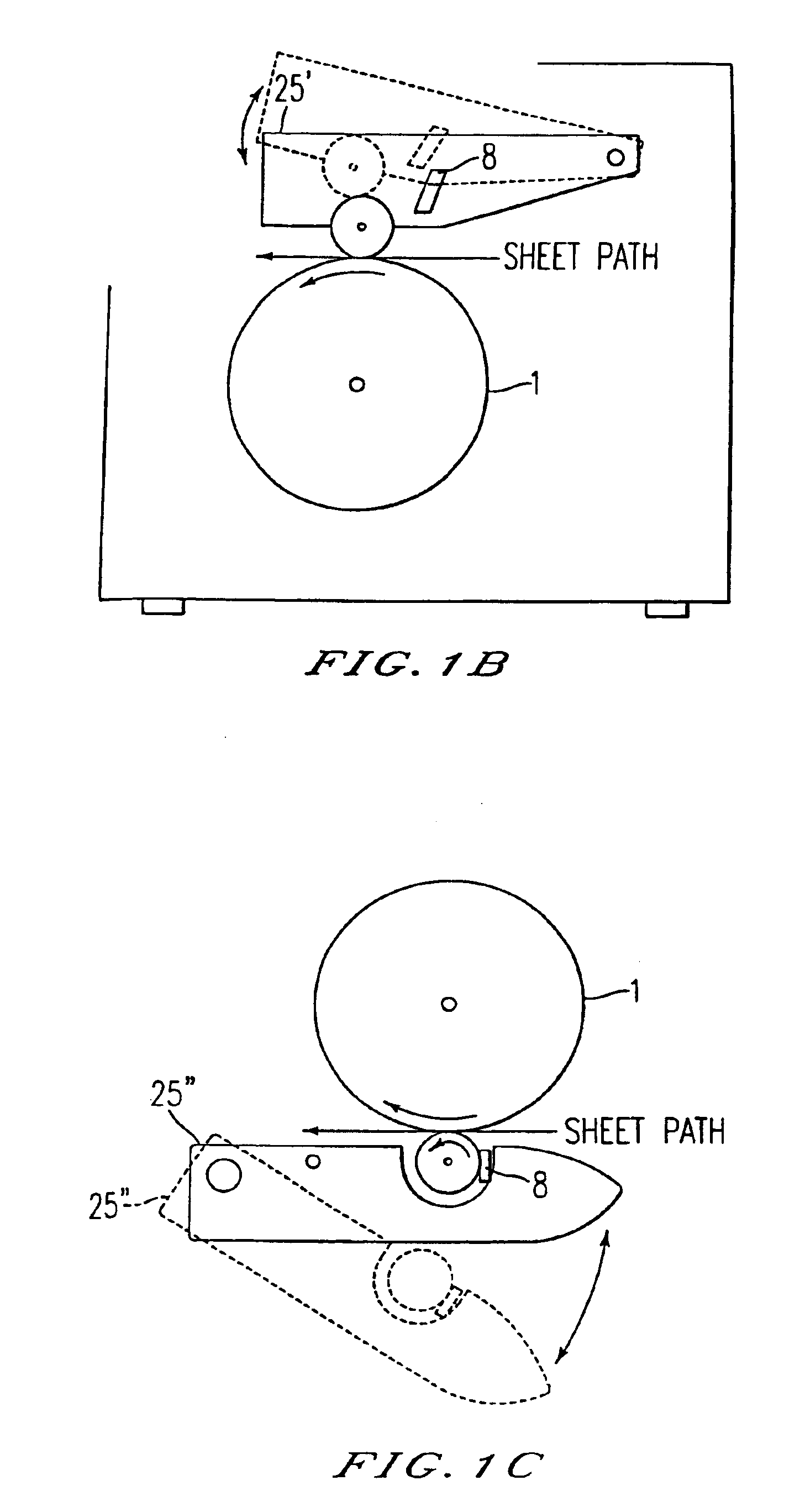
[0021]The present invention is explained in detail hereinafter using like reference numerals for identical or corresponding parts, throughout the several views, in which FIG. 1 is a schematic illustration of an image forming apparatus according to one embodiment of the present invention. As shown, the image forming apparatus 100 includes a photoconductive element or rotating image carrying element (e.g., a drum 1, a belt, or an intermediate transfer element). A charge roller 2 charges the surface of the drum 1. A writing device 3 forms an electrostatic latent image on the drum 1. A developing device 4 develops the electrostatic latent image by transferring toner to the drum 1. A transfer device (e.g., a contact type transfer roller 5, a belt, a brush, or a blade) transfers a developed image onto a sheet of paper P fed by a sheet feeding device 6. A sensing control system is provided with an optical sensor 8 and senses a toner density and detects a transfer sheet P. A control device ...


PUM


Abstract

A control system for an image forming device includes a sensor mounted on an optical path unobstructed by elements that are subject to wear for detecting a time varying signal representing reflected light from both a photoconductive element and a transfer sheet internal to the image forming device, a memory storing reference values, and a controller to control an image forming operation based on the reference values stored in the memory and the time-varying signal received from the sensor. The controller reads the time-varying signal from the sensor and compares the time-varying signal read to the reference values to determine a condition of the image forming device.

Description

CROSS-REFERENCE TO RELATED APPLICATIONS[0001]This application is a continuation application of, and claims priority to, Ser. No. 09 / 627,323, filed Jul. 27, 2000, which is a divisional of U.S. Ser. No. 09 / 241,856, filed Feb. 2, 1999, which claims priority to Japanese Application No. JP 10-036725 filed Feb. 2, 1998 and JP 10-368558, filed Dec. 8, 1998. The entire contents of these prior applications are incorporated herein by reference.BACKGROUND OF THE INVENTION[0002]1. Field of the Invention[0003]The present invention relates to an image forming apparatus including a sensing control system.[0004]2. Discussion of the Background[0005]In recent years, based on the increasing demand for smaller and less expensive configurations, various image forming apparatuses (e.g., copying machines, printers, facsimile machines and multi-function machines) having copying, facsimile and printer functions, have been designed. Accordingly, many of the individual parts, including the sensors, must be ma...

Claims


Application Information

Patent Timeline
Patent Type & Authority Patents(United States)
IPC IPC(8): G03G15/00B41J11/42B65H7/06B65H43/04G03G15/08
CPCG03G15/70G03G15/5041G03G2215/00042G03G2215/00392G03G2215/00548G03G2215/00616G03G2215/00721G03G2215/00544G03G15/00
Inventor OHORI, MAYUMITANAKA, MASARUMIZUISHI, HARUJIOHKAJI, HIROYUKITATSUMI, KENZOMIZUSAWA, HIROSHIAMEMIYA, KENZENBA, HIDEKIKISHI, FUMIO
Owner INTEL CORP
Learn More