Belt apparatus and image forming apparatus

Inactive Publication Date: 2005-05-24
RICOH KK
View PDF14 Cites 18 Cited by
  • Summary
  • Abstract
  • Description
  • Claims
  • Application Information

AI Technical Summary

Benefits of technology

[0012]An object of the present invention is to reduce

Problems solved by technology

In addition, both the direct and indirect transfer devices have a problem in that it is difficult to superimpose color toner images over one another in a multicol

Method used


Image

  • Belt apparatus and image forming apparatus
  • Belt apparatus and image forming apparatus
  • Belt apparatus and image forming apparatus

Examples


first embodiment

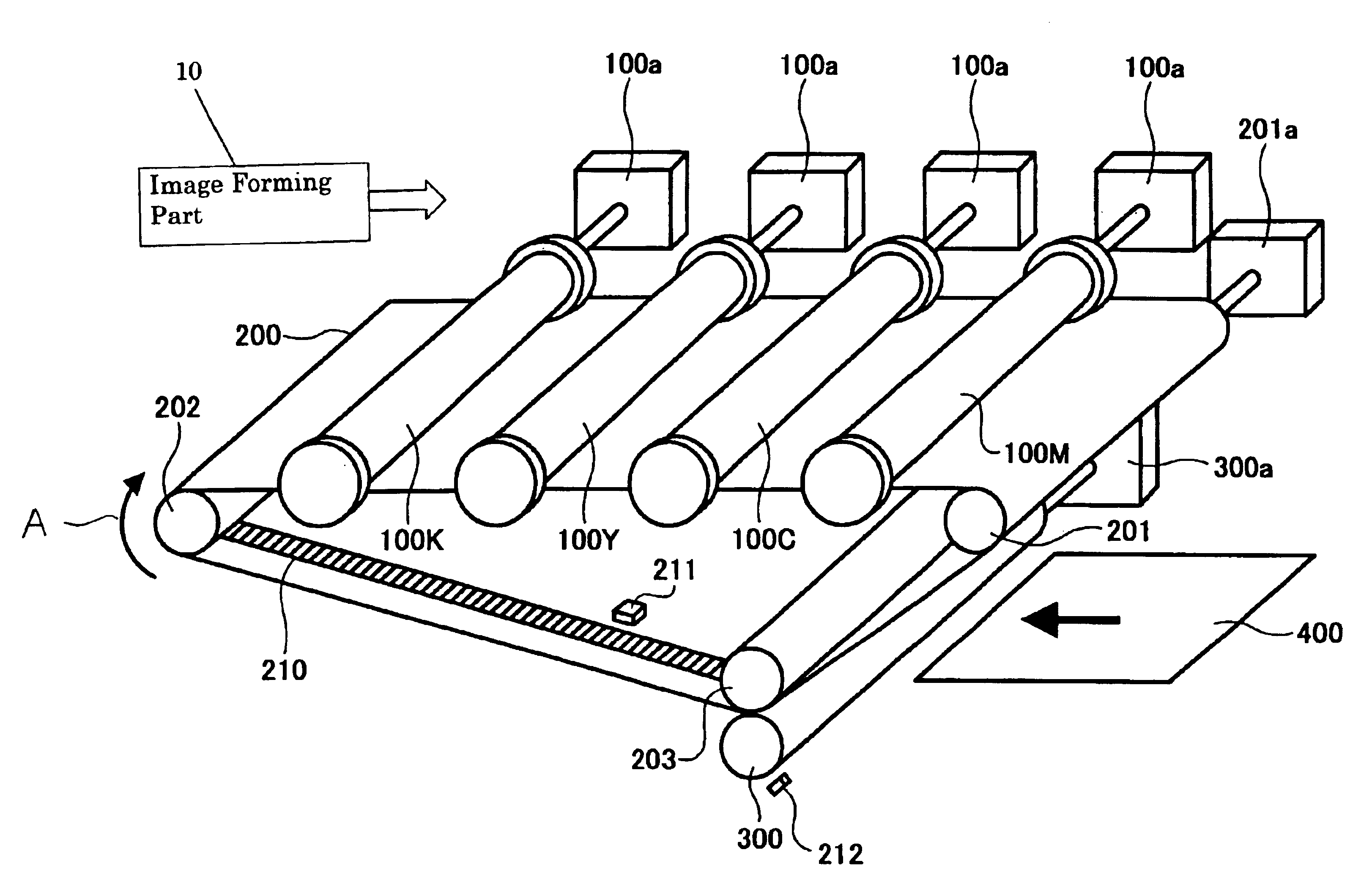
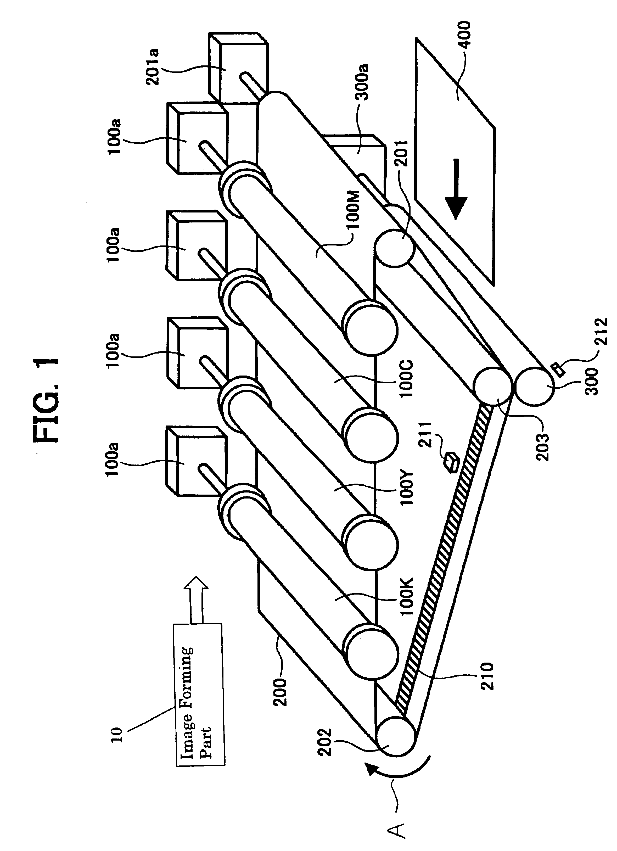
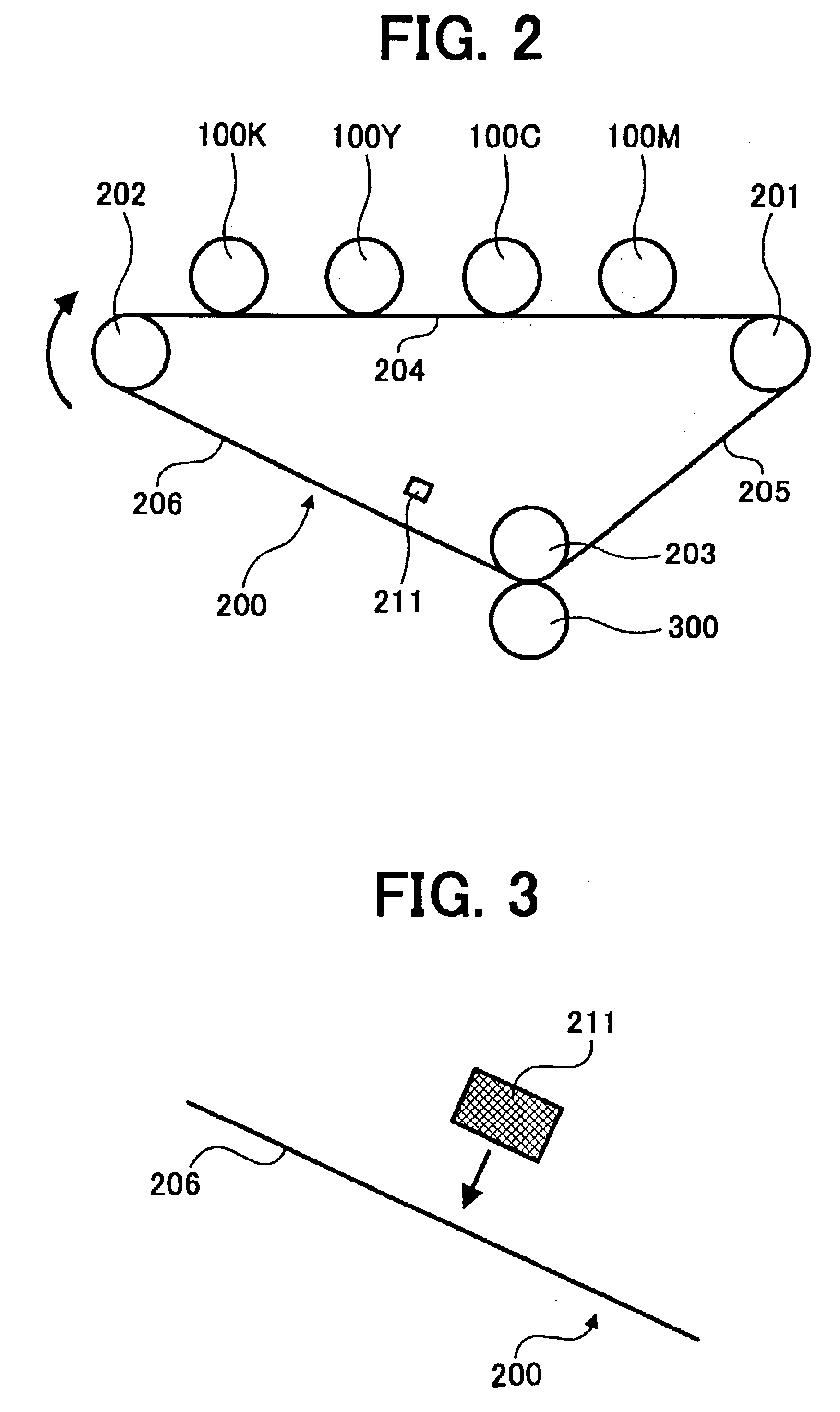
[0028]Referring now to the drawings wherein like reference numerals designate identical or corresponding parts throughout the several views, FIG. 1 is a perspective view of an image forming apparatus in accordance with the present invention, and FIG. 2 is a side view of the image forming device of FIG. 1. As seen in these figures, the image forming apparatus of this embodiment includes photo conductors 100K, 100Y, 100C, and 100M positioned along an image transfer belt 200. The photoconductors carry latent images formed by the image forming part 10. Each of the motors 100a drives a respective photo conductor. The photo conductors 100K, 100Y, 100C and 100M contain black, yellow, cyan and magenta toner, respectively. When the intermediate transfer belt 200 rotates in direction of arrow A, each black, yellow, cyan, magenta toners are transferred to the intermediate transfer belt 200 such that each color is overlapped to form a multicolor image. The intermediate transfer belt 200 is stre...

second embodiment

[0035]FIG. 6 is a perspective view of an image forming apparatus in accordance with the present invention, and FIG. 7 is a side view of the image forming device of FIG. 6. As seen in these Figures, the image forming apparatus of this embodiment includes photo conductors 150K, 150Y, 150C, and 150M positioned along an image transfer belt 251. The photoconductors carry latent images formed by the image forming part 10. Each of the motors 150a drives a respective photo conductor. The photo conductors 150K, 150Y, 150C and 150M contain black, yellow, cyan and magenta toner, respectively. When the intermediate transfer belt 250 rotates in direction of arrow B, each black, yellow, cyan, magenta toners are transferred to the intermediate transfer belt 250 such that each color is overlapped to form a multicolor image that is transferred to paper 450. The intermediate transfer belt 250 is stretched around driven roller 251, roller 252 and pressure roller 253. The driven roller 251 is driven by...


PUM


Abstract

A belt apparatus including a belt configured to rotate around a plurality of belt rollers, a belt speed detection system configured to detect a speed of the belt, and a contact roller configured to contact the belt. A control device is configured to control the contact roller based on a detected speed of the belt. An image forming apparatus includes an image forming part configured to form an image, a first image transfer device, a transfer belt configured to rotate around a plurality of belt rollers and to hold the image transferred by the first image transfer device, a transfer belt speed detection system configured to detect a speed of the transfer belt, and a second transfer roller configured to transfer the image held on the transfer belt to a paper. A control device configured to control the second transfer roller based on a detected speed of the transfer belt.

Description

CROSS-REFERENCE TO RELATED APPLICATIONS[0001]The present application claims priority to Japanese Patent Application No. 2002-103028 filed in the Japanese Patent Office on Apr. 4, 2002, Japanese Patent Application No. 2002-103032 filed in the Japanese Patent Office on Apr. 4, 2002, and Japanese Patent Application No. 2003-47623 filed in the Japanese Patent Office on Feb. 25, 2003, the disclosures of which are incorporated by reference herein in their entirety.BACKGROUND OF THE INVENTION[0002]1. Field of the Invention[0003]The present invention relates to a belt apparatus and an image forming apparatus such as a copier, a facsimile machine, a printer, or other similar image forming apparatus.[0004]2. Description of the Related Art[0005]Recently, the market is demanding color printers and color copiers. Such color printers and copiers are conventionally either a one drum type, which includes plural developing devices positioned around a photo conductor, or a tandem type having each dev...

Claims


Application Information

Patent Timeline
IPC IPC(8): G03G15/01B65H5/06G03G21/14G03G15/16G05D3/12H02P5/46
CPCG03G15/0131G03G2215/0119G03G2215/00139
Inventor TAKIGAWA, JUNYA
Owner RICOH KK
Why Eureka
Try Eureka