Systems and methods for controlling transmission power to reduce frequency interference

a transmission power and frequency interference technology, applied in the field of wideband radiocommunication system, can solve problems such as adversely affecting the operation of the phs system

Inactive Publication Date: 2005-05-24
KK TOSHIBA
View PDF5 Cites 8 Cited by
  • Summary
  • Abstract
  • Description
  • Claims
  • Application Information

AI Technical Summary

Benefits of technology

[0007]Another object of the present to provide a radio-communication device, a base station, and an up-link power controlling method which avoid adversely affecting the operation of a radiocommunication system having a nearby frequency band assigned.

Problems solved by technology

However, this means that the power amplifier is used at an operating point close to saturation.
If the transmit signal frequency in the W-CDMA mobile is close to 1920 MHz, the spread spectrum due to signal distortion by the power amplifier will extend to the frequency band of the PHS system, which can adversely affect the operation of the PHS system.

Method used


Image

  • Systems and methods for controlling transmission power to reduce frequency interference
  • Systems and methods for controlling transmission power to reduce frequency interference
  • Systems and methods for controlling transmission power to reduce frequency interference

Examples


first embodiment

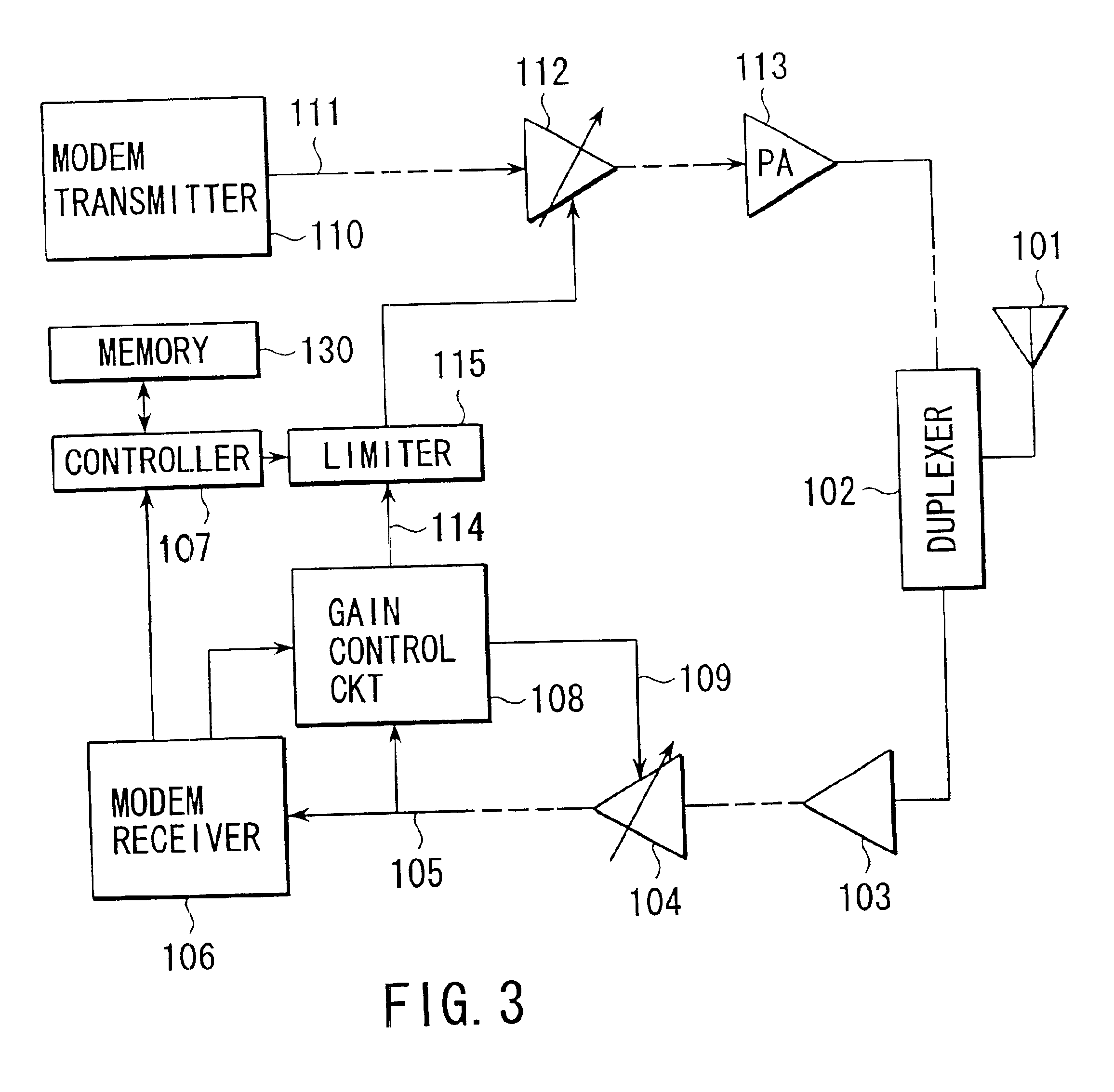
[0025]Referring now to FIG. 3, there is illustrated in block diagram form a radiocommunication device (hereinafter referred to as a mobile) according to the present invention.

[0026]A radio-frequency signal (down-link signal) transmitted from a base station (not shown) is received by an antenna 101 and then input through a duplexer 102 to a low-noise amplifier 103. An output signal of the amplifier 103, after, though not shown, passing through a filter for eliminating undesired signals outside the desired frequency band, a down-converter for frequency converting the received RF signal to an intermediate-frequency signal, and a filter for eliminating undesired signals apart in frequency from a desired signal, is applied to a gain controlled amplifier 104 where the output signal of the amplifier 103 is subjected to level adjustment. The level-adjusted signal is then converted into a baseband signal 105 by passing through a quadrature demodulator, a baseband filter, and a baseband ampli...

third embodiment

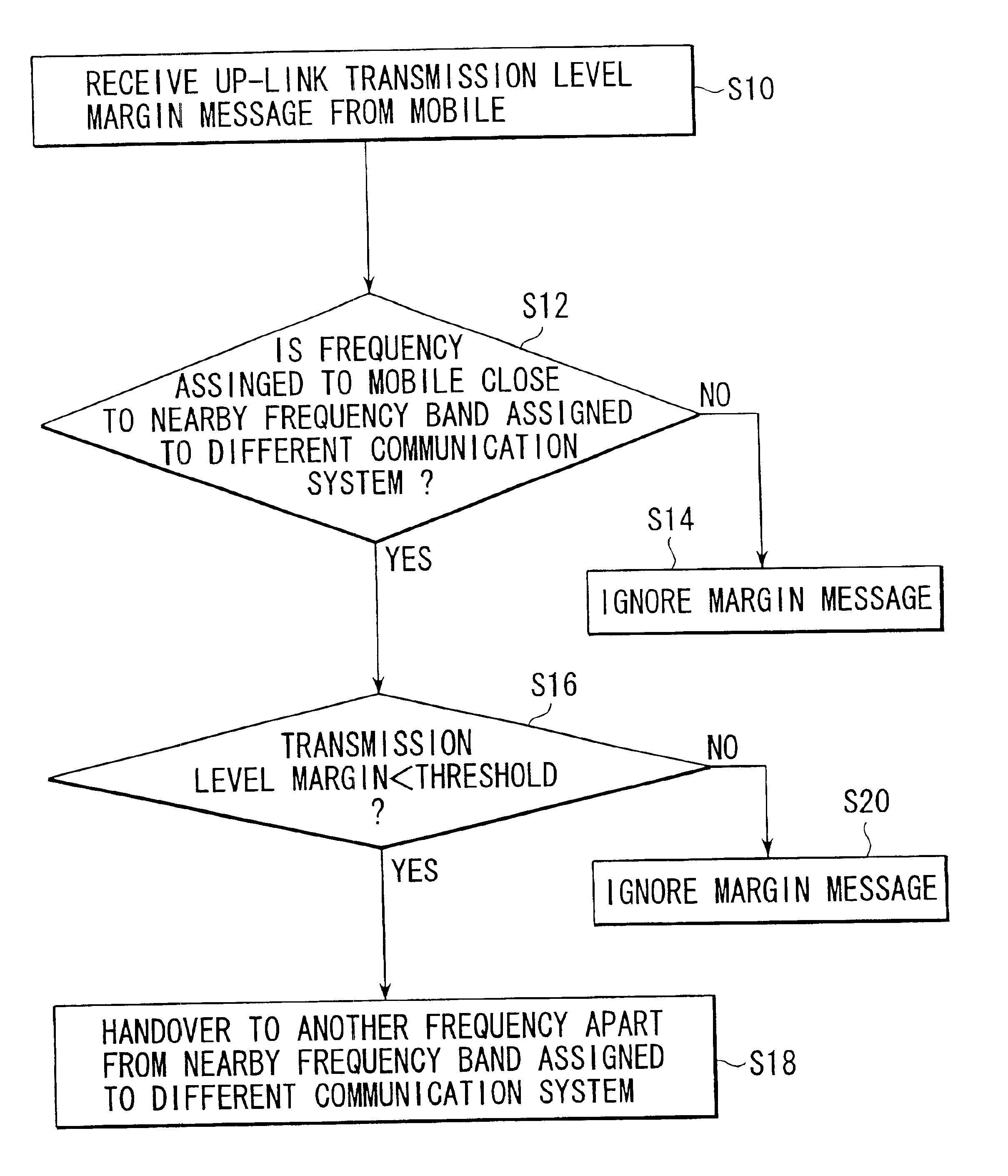
[0060]Additional advantages and modifications will readily occur to those skilled in the art. Therefore, the present invention in its broader aspects is not limited to the specific details, representative devices, and illustrated examples shown and described herein. Accordingly, various modifications may be made without departing from the spirit or scope of the general inventive concept as defined by the appended claims and their equivalents. For example, the example of the radiocommunication systems is not limited to the above example. Further, the third embodiment includes two judgment steps S16 and S46 in FIG. 9 and steps S36 and S56 in FIG. 10. It is possible to set the threshold in these two steps to different values in order to have a hysteresis characteristics. If these thresholds are set to the different values, it is desirable to make the threshold for margin of step S16 greater than that of step S42 and make the threshold for level of step S36 lower than that of step S52 i...


PUM


Abstract

For use in a radiocommunication system using a frequency band close to a frequency band of a different radiocommunication system, a radiocommunication device, or a mobile, is controlled so that a maximum of transmission power is set according to an up-link frequency in use. The closer the up-link frequency in use is to the frequency band of the different radiocommunication system, the lower the maximum of transmission power is set.

Description

CROSS-REFERENCE TO RELATED APPLICATIONS[0001]This application is based upon and claims the benefit of priority from the prior Japanese Patent Application No. 2000-090233, filed Mar. 29, 2000, the entire contents of which are incorporated herein by reference.BACKGROUND OF THE INVENTION[0002]The present invention relates to a wideband radiocommunication system such as CDMA (Code Division Multiple Access), and more specifically, a radio-communication device having an up-link power control function and a base station, which are used in the wideband communication system, and a method of controlling the up-link power.[0003]In recent years, a radiocommunication system has begun to be put into practice which is based on the CDMA technique in which, by spreading an information-bearing transmit signal with a code to produce a wideband spread signal, channels can be assigned on a code-by-code basis. In 2001, a W-CDMA system will be put into practice which allows more information to be transmit...

Claims


Application Information

Patent Timeline
Patent Type & Authority Patents(United States)
IPC IPC(8): H04B7/005H04W52/04H04B7/26H04J13/00H04W52/40H04W76/02
CPCH04W52/367H04W28/048Y02B60/50H04W88/08H04W28/04
Inventor HAYASHIHARA, MIKIO
Owner KK TOSHIBA
Why Eureka
Try Eureka