
Gun barrel having a muzzle brake

a technology of muzzle brake and barrel, which is applied in the direction of muzzle attachment, weapon components, weapons, etc., can solve the problems of complicated machining of muzzle brake, and achieve the effect of high hitting accuracy and easy machined muzzle of the barrel

Inactive Publication Date: 2005-05-31
RHEINMETALL W & M GMBH
View PDF25 Cites 28 Cited by
  • Summary
  • Abstract
  • Description
  • Claims
  • Application Information

AI Technical Summary

Benefits of technology

[0005]It is the object of the invention to provide an arrangement comprising a gun barrel and a muzzle brake, in which, during firing, no high stresses comparable to those in the known barrels are exerted on the parts of the muzzle brake that are detachably connected to the barrel.
[0009]A further distinguishing feature of the barrel / muzzle brake arrangement according to the invention is that the muzzle of the barrel can be machined very easily. The arrangement further ensures that projectiles pass smoothly through the region of the muzzle brake, and there is no negative influence on the jump-error angle, which guarantees a high hitting accuracy.
[0010]The axially adjacent openings of the barrel in the muzzle region are preferably offset from one another. This takes into account the stability requirements on the barrel, on the one hand, and assures the unimpeded passage of projectiles in this barrel region, on the other.

Problems solved by technology

A drawback associated with this known arrangement is that the use of such muzzle brakes dictates a complicated machining of the respective gun muzzle, because relatively high stresses (high acceleration forces, high tensile forces due to the braking effect) act on the muzzle brake when the gun is fired, so the threaded connection that fixes the muzzle brake to the gun barrel must be designed with these stresses in mind.

Method used


Image

  • Gun barrel having a muzzle brake
  • Gun barrel having a muzzle brake
  • Gun barrel having a muzzle brake

Examples


Embodiment Construction

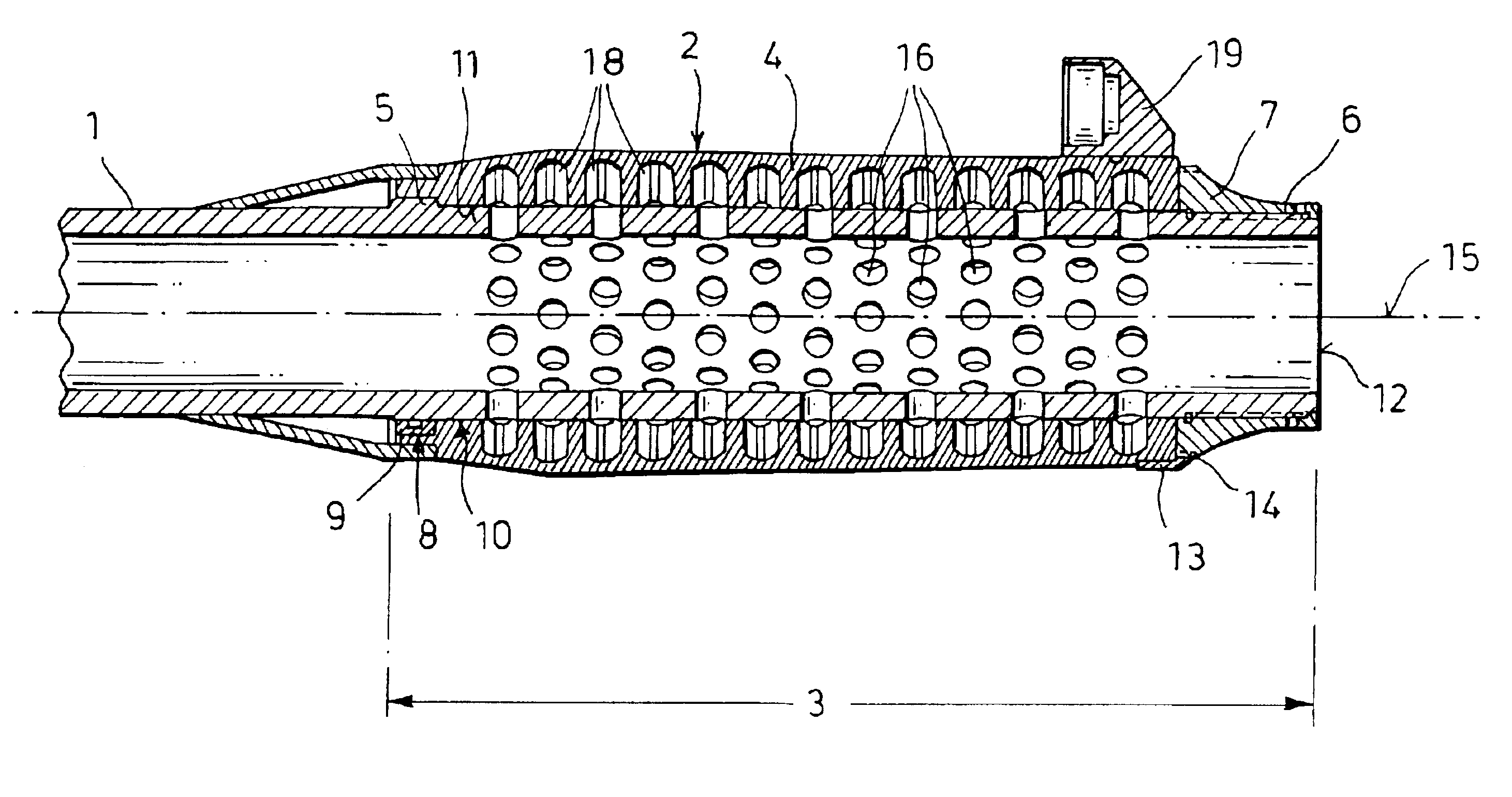
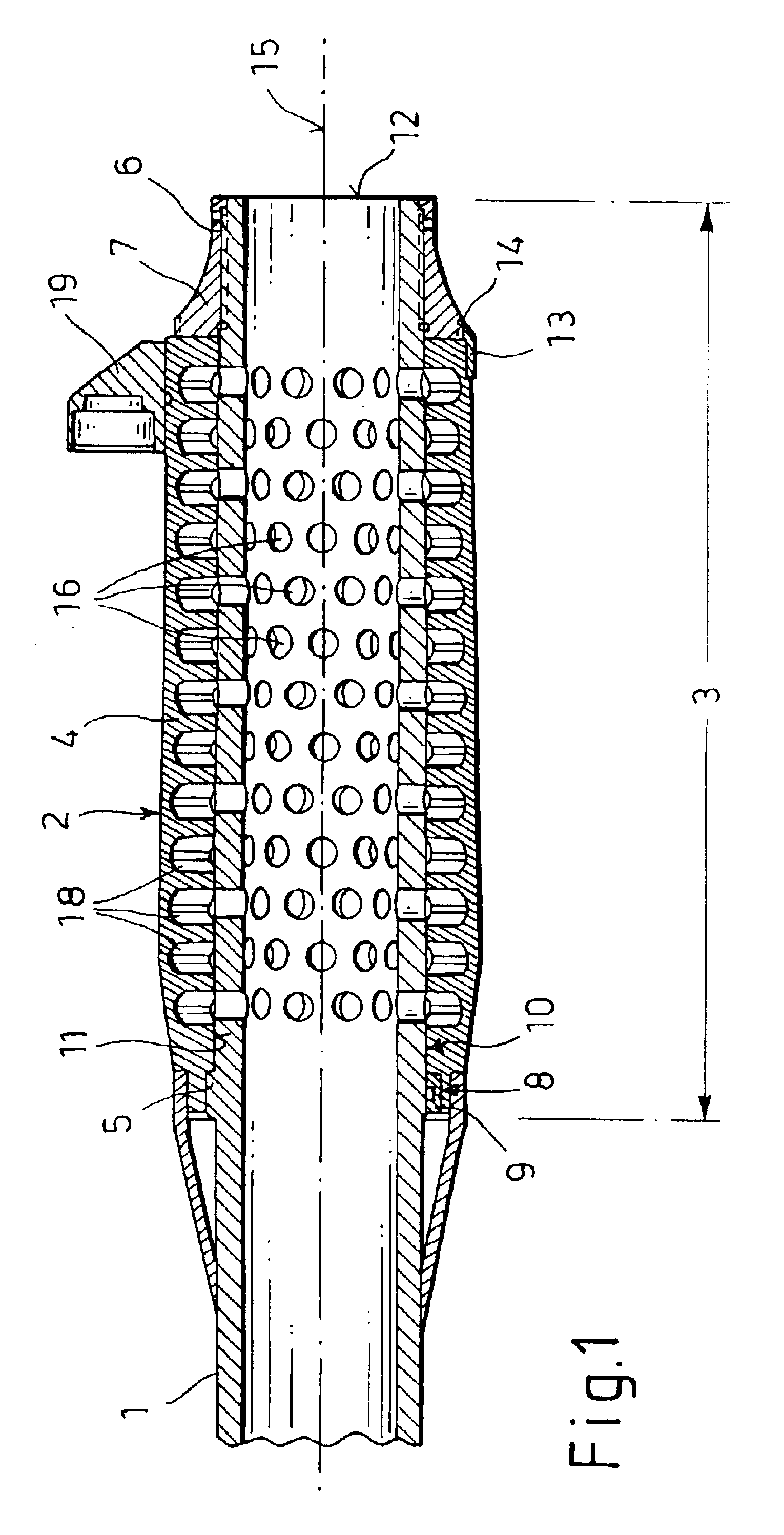
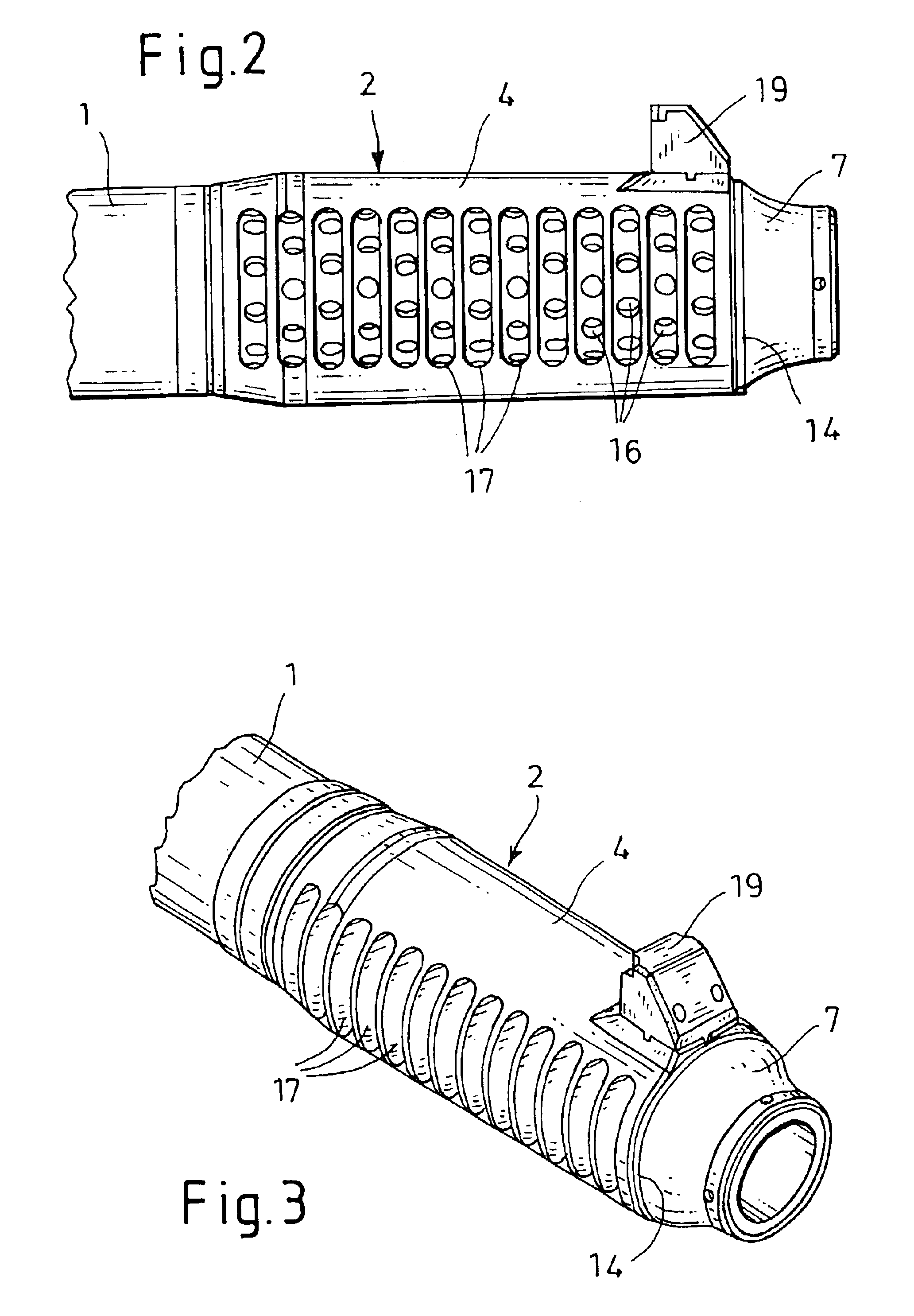
[0017]FIGS. 1 through 3 depict a large-caliber gun barrel 1 of a tank gun, which is provided on the front with a muzzle brake 2. The muzzle brake 2 encompasses the muzzle region 3 of the barrel 1 and a jacket tube 4 that is disposed over the muzzle region 3 and is supported at the rear against an annular stop 5 of the barrel 1, and is held at the front by a screw ring 7 that can be screwed onto a thread 6 on the outer surface of the barrel 1.

[0018]To secure the jacket tube 4 against rotating, a spline and keyway connection 8 is provided and includes a longitudinally extending spline or key 9 disposed in the jacket tube 4. This spline or key 9 extends into a groove, not shown, in the annular stop 5 of the barrel 1.

[0019]To assure fast assembly and a secure seating of the jacket tube 4 on the barrel 1, the outside surface 10 of the barrel 1 and the inside surface 11 of the jacket tube 4 taper slightly in conical fashion toward the muzzle 12 of the barrel 1.

[0020]A securing piece 13, w...


PUM


Abstract

A gun barrel having a muzzle brake (2), especially for large-caliber guns, in which the muzzle brake (2) includes a tubular piece that has openings (16) around its circumference, and a jacket tube (4), which surrounds the tubular piece and has diametrically opposite gas-exit openings (17) that extend perpendicular to the bore longitudinal axis (15). To provide an arrangement comprising a barrel (1) and a muzzle brake (2) that minimizes the firing stresses on the parts of the muzzle brake (2) that are detachably connected to the barrel (1), the muzzle region (3) of the barrel (1) itself is used as a component of the muzzle brake (2. That is, the muzzle region of the barrel is provided with a plurality of openings (16) arranged in ring formation around the barrel (1), and the attached the jacket tube (4) is provided with slot-shaped gas-exit openings (17) over this muzzle region (3).

Description

CROSS REFERENCE TO RELATED APPLICATION[0001]This application claims the priority of German Patent Application DE 102 07 256.6 filed Feb. 21, 2002 which is incorporated herein by reference.BACKGROUND OF THE INVENTION[0002]The invention relates to a gun barrel having a muzzle brake, especially for large-caliber guns.[0003]European Patent EP 0 085 754 B1 discloses a gun barrel in which a separate muzzle brake is attached to the muzzle end of the barrel in order to reduce the recoil energy. The muzzle brake includes a tubular piece that ends flush with the barrel and has radial bores around its circumference, with the inside diameter of the tube being identical to the caliber. The brake further includes a jacket tube, which has diametrically opposite gas-exit openings that extend perpendicular to the longitudinal axis of the bore.[0004]A drawback associated with this known arrangement is that the use of such muzzle brakes dictates a complicated machining of the respective gun muzzle, be...

Claims


Application Information

Patent Timeline
Patent Type & Authority Patents(United States)
IPC IPC(8): F41A21/36F41A21/00F41A5/26
CPCF41A21/36
Inventor BREUER, HEINZ-GUNTER
Owner RHEINMETALL W & M GMBH
Learn More