Device for cooling and heating a motor vehicle

a technology for motor vehicles and devices, which is applied in the direction of light and heating equipment, machines/engines, indirect heat exchangers, etc., can solve the problems of increasing fuel consumption and exhaust emissions, increasing the limits of the amount of heat generated by the internal combustion engine that remains available, and increasing the amount of heat input into the cooling water, so as to accelerate the warming up of the engine and increase the thermal output of the system. , the effect of increasing the thermal output of the system

Inactive Publication Date: 2005-05-31
ROBERT BOSCH GMBH
View PDF16 Cites 46 Cited by
  • Summary
  • Abstract
  • Description
  • Claims
  • Application Information

AI Technical Summary

Benefits of technology

[0013]The claimed apparatus according to the invention, which is for cooling and / or heating a motor vehicle, has the advantage over the prior art that the heat dissipation into the associated cooler segment can be regulated as needed by means of the at least one bypass line and the associated bypass valve, which are associated with at least one secondary cooler segment and are situated in parallel to this secondary cooler segment in the cooling and heating system of the motor vehicle. The bypass valve and the associated bypass line make it possible to bypass the cooler as needed. As a result, the full of thermal output of the secondary unit, for example a generator or starter, can be used to accelerate the warming up of the engine and to increase the thermal output of the system.

Problems solved by technology

On the other hand, the significantly increased efficiency of modern engines, for example direct injecting diesel engines, places ever increasing limits on the amount of heat generated by the internal combustion engine that remains available for other uses in the cooling and heating system of the vehicle.
In some operating states of an engine, for example in the case of a cold start, when used for short trips, or even when the vehicle is traveling down long descents, the amount of heat input into the cooling water, which heat can be supplied by the engine itself, is no longer sufficient.
As a result, the engine and its catalytic converter do not reach the optimal operating temperatures in the available amount of time, which leads to increased fuel consumption and exhaust emissions.
These secondary heaters are quite expensive and also have the disadvantage that they must be installed in the generally cramped engine compartment of a motor vehicle and therefore incur costs that are not insignificant.
One main problem in imparting dissipated energy from electronic power semiconductors, for example also from starters or generators, into the cooling circuit of a vehicle lies in preventing the permissible component temperature of the semiconductor elements from being exceeded when cooling water temperatures are high.
The heat exchanger system disclosed in DE 199 60 960 C1 is very costly and complex so that in addition to the increased susceptibility of this system, its high costs must also be viewed as a non-negligible disadvantage.

Method used


Image

  • Device for cooling and heating a motor vehicle
  • Device for cooling and heating a motor vehicle
  • Device for cooling and heating a motor vehicle

Examples


Embodiment Construction

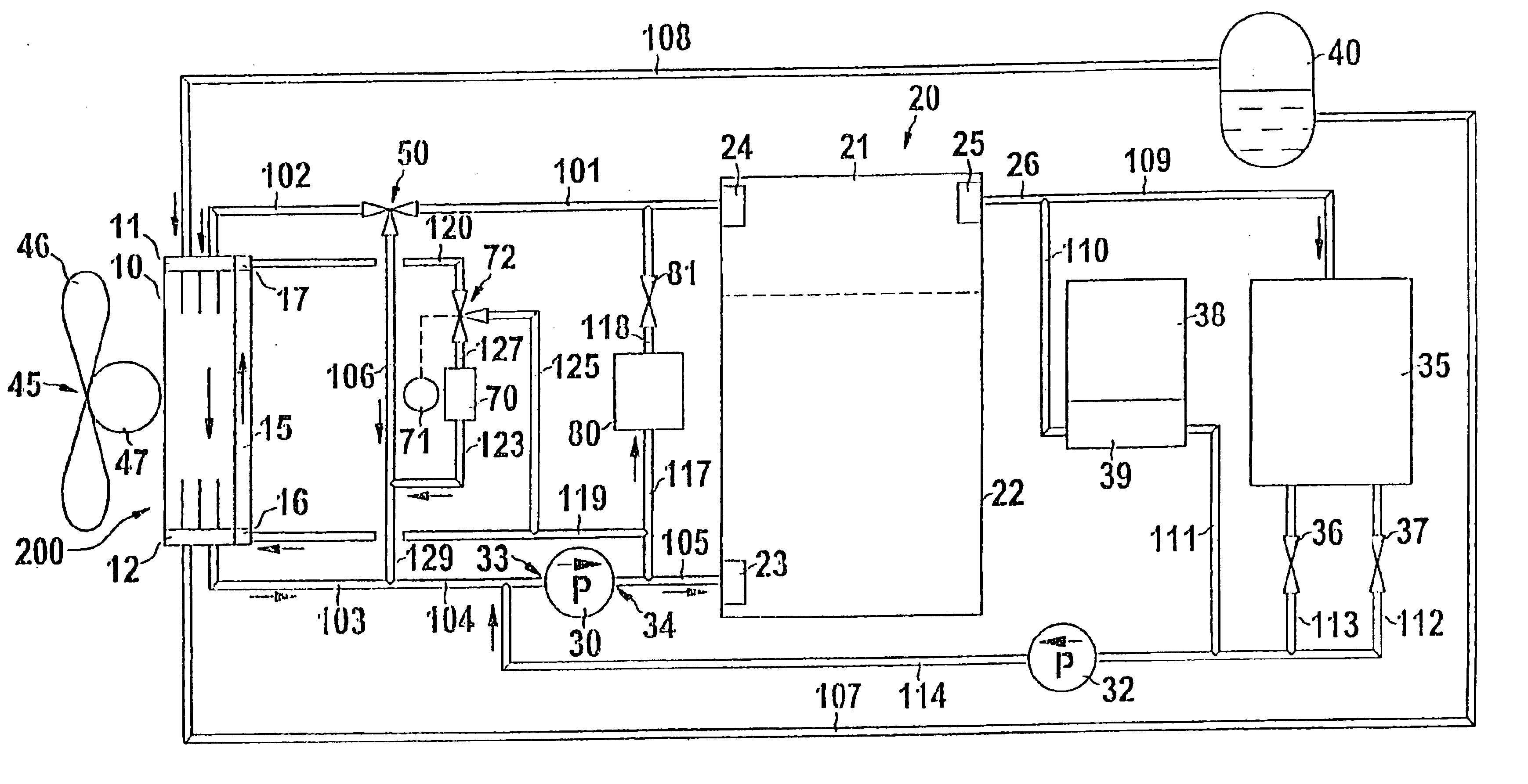
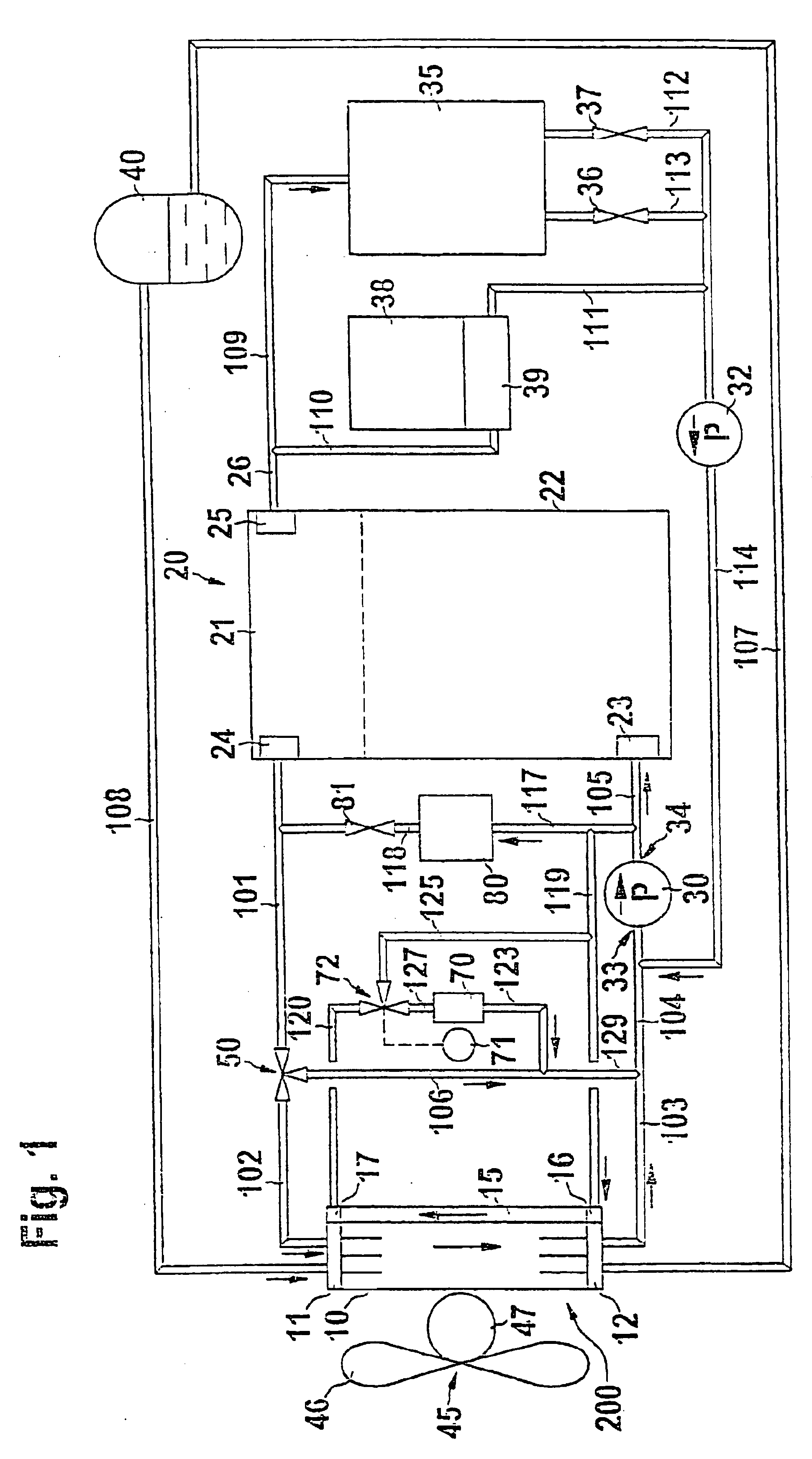
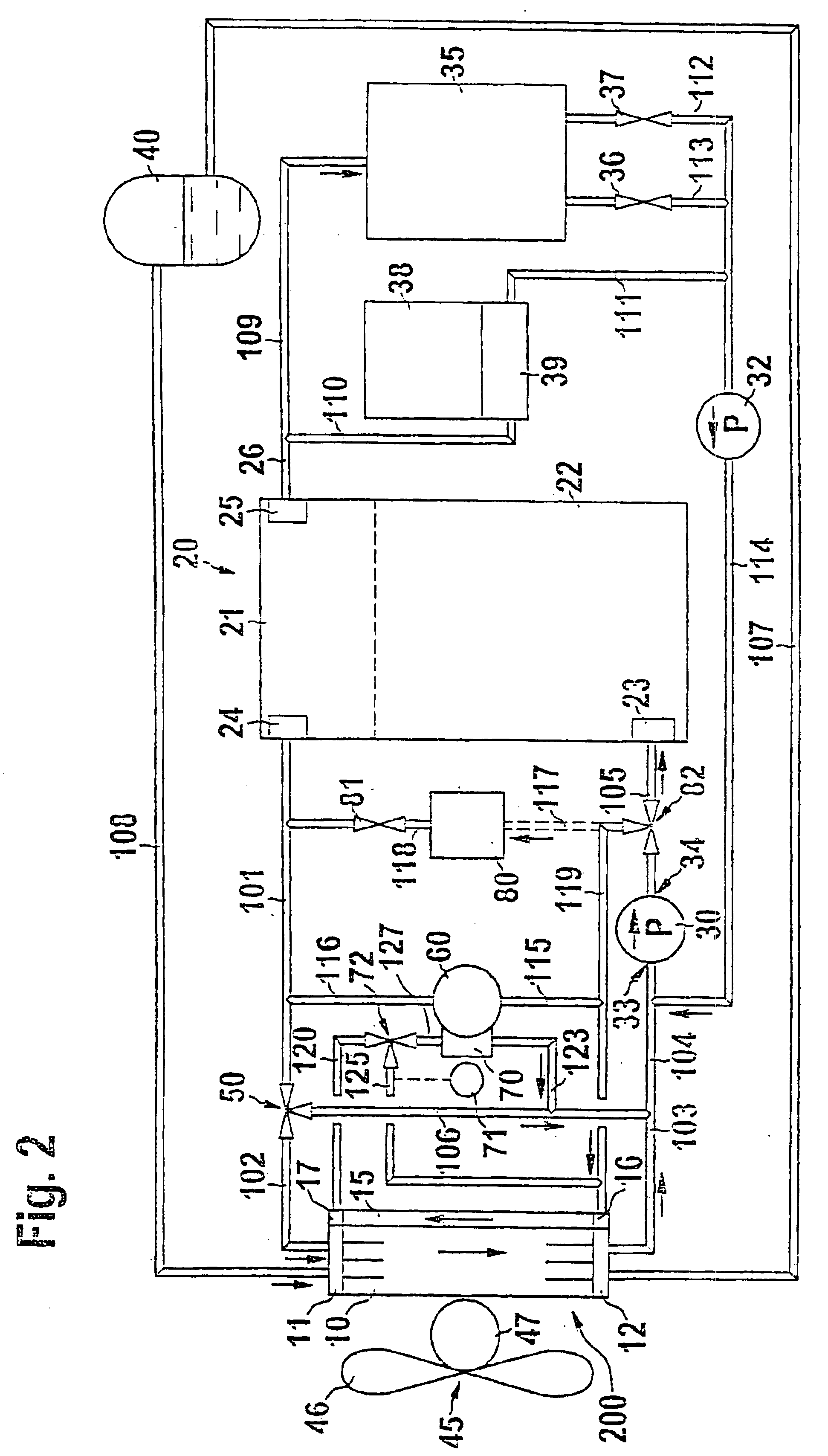
[0039]The first description will be of those components of the apparatus according to the invention for cooling and / or heating a motor vehicle, which are essentially the same for the embodiments according to FIGS. 1 to 3.

[0040]In the embodiments of the cooling system according to the invention shown in FIGS. 1 to 3, the apparatus includes a main cooler segment 10, which has a main cooler inlet 11 and a main cooler outlet 12. Adjacent to the main cooler segment 10, there is a cooling fan 45. The cooling fan 45 has a fan 46 and a fan motor 47. A compensation receptacle 40 is connected to the main cooler inlet 11 via a line section 108 and is connected to the main cooler outlet 12 via a line section 107.

[0041]The apparatus according to the invention, which is also referred to below in the same sense as a cooling system, serves primarily to cool an internal combustion engine 20. In a simplified representation, the engine 20 has a cylinder head 21 and an engine block 22. A coolant inlet ...


PUM


Abstract

The current invention relates to an apparatus for cooling and / or heating a motor vehicle, with at least one coolant pump for circulating a coolant in a cooling and heating system, with a main cooler segment, which has a main cooler inlet and a main cooler outlet, wherein the main cooler inlet is at least intermittently connected to at least one coolant outlet of an engine to be cooled, in particular an internal combustion engine, of the vehicle, and its main cooler outlet is connected to at least one coolant inlet of the engine, and with at least one other, secondary cooler segment provided in addition to the main cooler segment and at least one other unit to be cooled, which is connected to the cooling and heating system, and the apparatus have at least one bypass line with a bypass valve, which is associated with the at least one secondary cooler segment and is disposed parallel to this secondary cooler segment in the cooling and heating system of the motor vehicle.

Description

BACKGROUND OF THE INVENTION[0001]The current invention relates to an apparatus for cooling and / or heating a motor vehicle.[0002]In modern vehicles, various units secondary to the engine are used, which are referred to below as units or secondary units. Such secondary units can be electric machines such as starters or generators, or also oil coolers and air conditioning compressors. In many cases, it is necessary to cool the secondary units in a manner similar to that of the engine.[0003]On the other hand, the significantly increased efficiency of modern engines, for example direct injecting diesel engines, places ever increasing limits on the amount of heat generated by the internal combustion engine that remains available for other uses in the cooling and heating system of the vehicle. In some operating states of an engine, for example in the case of a cold start, when used for short trips, or even when the vehicle is traveling down long descents, the amount of heat input into the ...

Claims


Application Information

Patent Timeline
Patent Type & Authority Patents(United States)
IPC IPC(8): F01P7/16F01P7/14F01P3/00F01P3/18F01P3/20
CPCF01P7/165F01P7/164F01P2003/187F01P2007/146F01P2023/08F01P2070/00F01P2050/30F01P2060/02F01P2060/08F01P2060/185F01P2050/24B60H1/00
Inventor HOHL, REINERSCHMITT, MANFREDMANN, KARSTENKAEFER, OLIVER
Owner ROBERT BOSCH GMBH
Why Eureka
Try Eureka