Bidirectional printing method and apparatus with reduced color unevenness

a bidirectional printing and color uneven technology, applied in the direction of printing mechanisms, spacing mechanisms, printing, etc., can solve the problems of band color non-uniformity, color non-uniformity in the form of bands, and color non-uniformity attributable to scanning directions, so as to reduce the color non-uniformity

Inactive Publication Date: 2005-05-31
CANON KK
View PDF35 Cites 23 Cited by
  • Summary
  • Abstract
  • Description
  • Claims
  • Application Information

AI Technical Summary

Benefits of technology

[0017]Accordingly, it is a principal object of the present invention to provide a printing apparatus, a printing method and a print wherein the color non-uniformity attributable to the scanning directions can be reduced even if a bi-directional color print is carried out with different amounts of ink deposited.
[0018]It is another object of the present invention to provide a printing apparatus, a printing method and a print wherein the occurrence of the color non-uniformity attributable to the scanning direction is prevented irrespective of the print data with different amounts of ink deposited.
[0024]With such a structure, the pixel areas of a process color including a secondary color, arranged in a predetermined direction such as the raster scan direction, are dominantly provided by application of the inks in different application orders, and therefore, the orders of applications are substantially the same irrespective of the scanning directions so that generation of the color non-uniformity attributable to the order of applications of the inks can be reduced.

Problems solved by technology

However, the bi-directional printing type is disadvantageous in that it involves an essential problem in that the order of deposition, application or shot of the inks of different colors is different between the forward direction of the main-scanning and the backward direction thereof, depending on the structure of the recording head, and therefore, color non-uniformity in the form of bands results.
The problem arises from the order of the ink applications, and therefore, a difference in the coloring more or less appears when different color dots are overlaid with each other even slightly.
Therefore, the band color non-uniformity occurs due to the difference in the coloring.
However, the conventional technique 1) does not provide a fundamental solution, and the throughput is significantly lower when a color image is printed.
Conventional technique 3) is equivalent to using two independent sets of recording heads even if the recording heads for the forward path and the backward path are built in the same substrate, and therefore, a color non-uniformity arises due to a large color difference in the form of bands attributable to the difference of the properties of different heads.
For example, due to the difference in the data ratio of the forward path data to the backward path data, the temperature of the recording head may be different, and there arises a difference in the ejection amounts between the recording heads, which would result in the color non-uniformity in the form of bands.

Method used


Image

  • Bidirectional printing method and apparatus with reduced color unevenness
  • Bidirectional printing method and apparatus with reduced color unevenness
  • Bidirectional printing method and apparatus with reduced color unevenness

Examples


embodiment 1

(Embodiment 1)

[0062]FIG. 3 is a partial schematic view of a major part of a recording head portion of a head cartridge 1. In this Figure, designated by 100 is a first recording head for ejecting cyan ink (C1). Designated by 101 is a first recording head for ejecting magenta ink (M1). Designated by 102 is a first recording head for ejecting yellow ink (Y1). Designated by 103 is a second recording head for ejecting yellow ink (Y2). Designated by 104 is a second recording head for ejecting magenta ink (M2). Designated by 105 is a second recording head for ejecting cyan ink (C2). Additionally, a recording head for ejecting Bk ink may be used.

[0063]The head cartridge 1 is constituted by such recording heads.

[0064]In head cartridge 1, each of the recording heads includes a plurality of ejection nozzles. For example, the recording head 100C1 includes cyan ejection nozzles 110 for ejecting a relatively larger size of droplet of cyan ink. The recording head 101M1 includes magenta ejection no...

embodiment 2

(Embodiment 2)

[0111]The combinations of dots are not limited to those described in the foregoing, but various combinations are usable. In FIG. 3, when the secondary color is to be printed, the dot-on-dot structure necessarily results, but this is not limiting, and the dot arrangement with which the dots do not tend to overlap with each other when the binarization process is effected is possible.

[0112]FIG. 10 shows an embodiment in which the dots are allotted in such a manner. The dot arrangement of FIG. 10 is similar to that of FIG. 3, but an arrangement in which the dots are separated or deviated (pixels 140-147) is added to the previous dot arrangement (pixels 130-139).

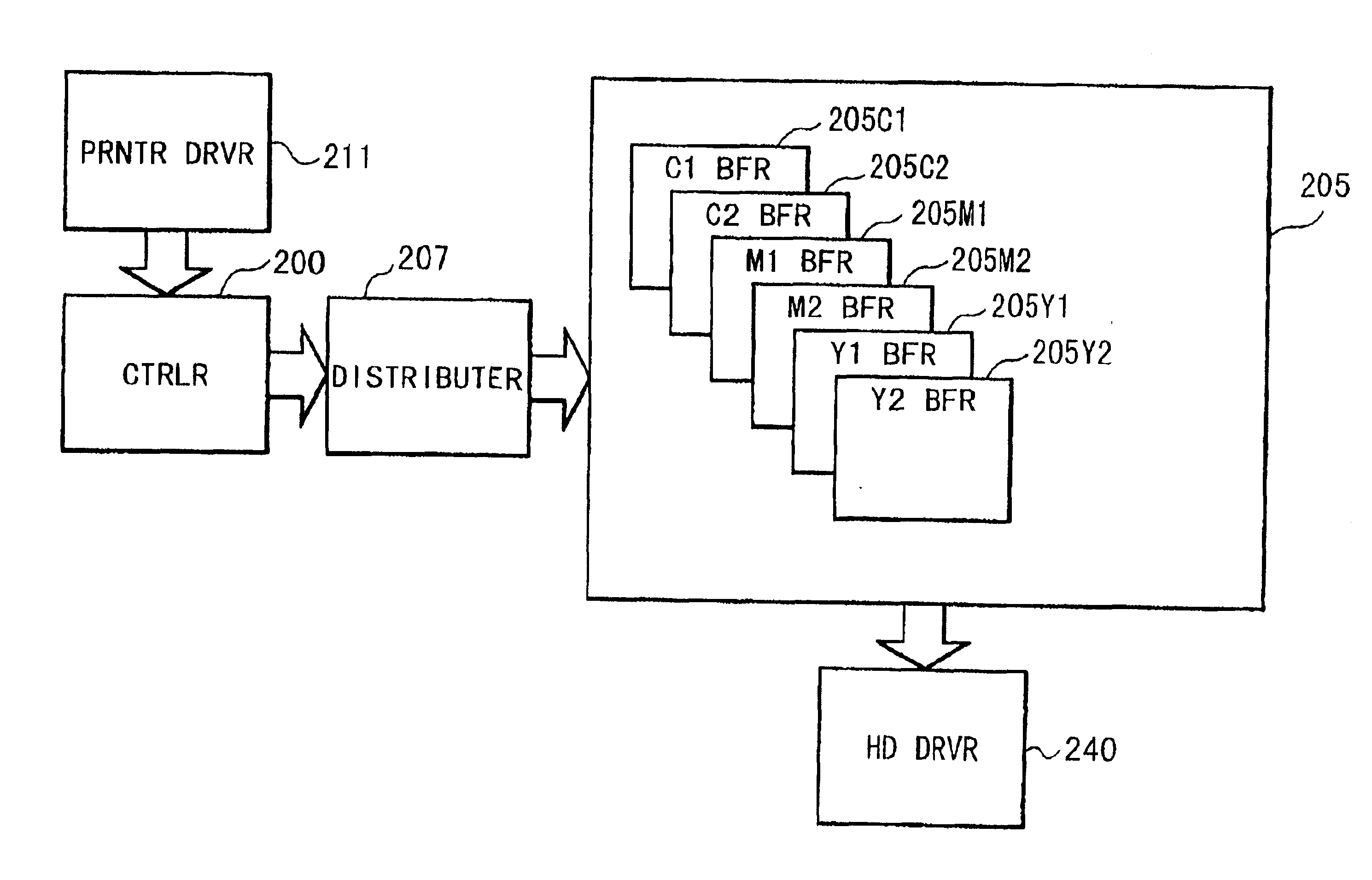
[0113]For example, at level 6, pixels 140, 141 at which the relatively smaller dots are split (not dot-on-dot) are added. By the distribution circuit, the data are stored in the buffer such that incidence probabilities of the pixels 131, 132, 140, 141, at which the level is at 6, are substantially equal along the ra...

embodiment 3

(Embodiment 3)

[0123]In Embodiment 1 described hereinbefore, one pixel is constituted by a pair of two dots of the same size, and the order of shots of a pair of different size dots of the same color ink is symmetrical, at least for one color. In such examples, one pixel is constituted by a pair of two dots, and therefore, the examples are preferable when the maximum density of print is desirable such as when the images are formed on an OHP sheet. When the maximum density is not required, the maximum density may be provided by the relatively larger dot.

[0124]In Embodiment 2, for high density portions, the order of shots of the same coloring is symmetrical at least for one color as in the foregoing Embodiments, and in the half-tone portions, use is made of a symmetrical recording head for bidirectional printing, and the combinations of the used recording heads are switched between when the recording heads scan in the forward direction and when they scan in the backward direction. By d...


PUM


Abstract

A printing apparatus, which forms a color image by applying different color inks to a printing material while bi-directionally moving the recording head to scan the recording material, includes a changing unit for changing an order of applications of the inks of different colors to be applied at least at one amount for printing a secondary color to a secondary color pixel area; and a forming unit for forming the secondary color while making the order of applications of the inks to at least one of a plurality of the secondary color pixel areas arranged along a predetermined direction different from the order of another, by the changing unit.

Description

FIELD OF THE INVENTION AND RELATED ART[0001]The present invention relates to a bi-directional printing apparatus and a bi-directional printing method for effecting color printing by scanning bi-directionally a printing material with a recording head for applying a plurality of (different) color inks at different ink amounts to the printing material, and more particularly to a bi-directional printing apparatus, a bi-directional printing method and a print wherein color non-uniformity attributable to the bi-directional color print operation is prevented.[0002]In the field of a printing apparatus, particularly an ink-jet type printing apparatus, increase of a recording speed for a color print is desired. To meet this desire, increase of the length of the recording head, increase of the frequency of actuation of the recording head, and bi-directional printing are generally considered. Bi-directional printing is advantageous in that required energy is less concentrated than in unidirecti...

Claims


Application Information

Patent Timeline
Patent Type & Authority Patents(United States)
IPC IPC(8): B41J19/14B41J2/21B41J19/00B41J2/205B41J19/18
CPCB41J2/2125B41J19/147B41J2/2132
Inventor OTSUKA, NAOJINISHIKORI, HITOSHIIWASAKI, OSAMUCHIKUMA, TOSHIYUKI
Owner CANON KK
Why Eureka
Try Eureka