Lamp unit assembling method and lamp unit mounting structure

Inactive Publication Date: 2005-05-31
YAZAKI CORP
View PDF20 Cites 14 Cited by
  • Summary
  • Abstract
  • Description
  • Claims
  • Application Information

AI Technical Summary

Benefits of technology

[0058]Consequently, a worker does not need to perform aligning so as to simultaneously fix the design potion to the interior wall member. This facilitates the assembling of the lamp unit and the

Problems solved by technology

This complicates the assembling operation that is overhead work performed in a narrow working space.
Consequently, good workability is difficult to obtain.
Especially because of the fact that the connection states of the connectors 40 and 41 cannot be visually checked by a worker, this conventional method has encountered a problem of poor connection reliability.
Further, as the manufacturing costs of the components increase, the assembling thereof is complicated more and more.
Consequently

Method used


Image

  • Lamp unit assembling method and lamp unit mounting structure
  • Lamp unit assembling method and lamp unit mounting structure
  • Lamp unit assembling method and lamp unit mounting structure

Examples


Example

First Embodiment

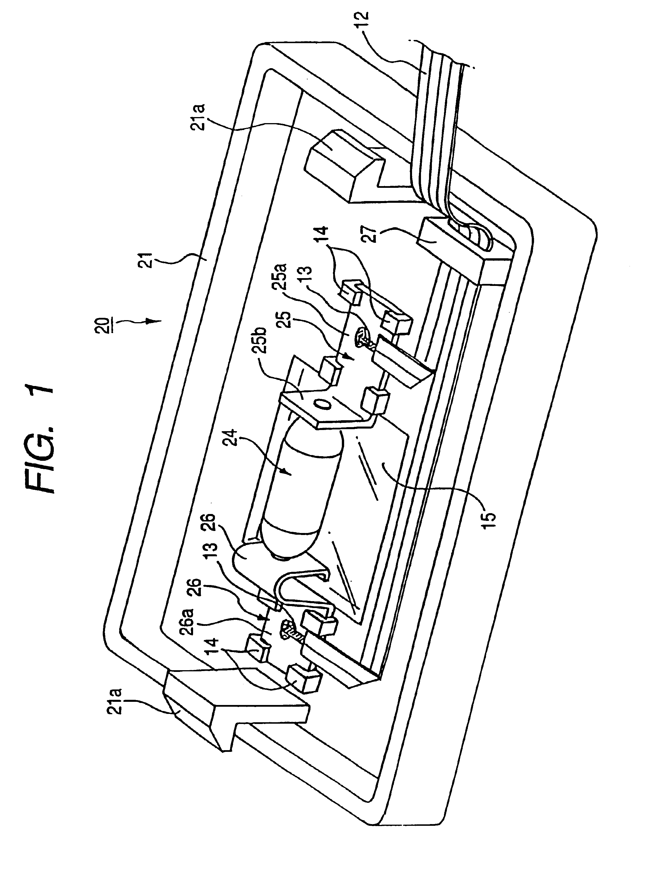
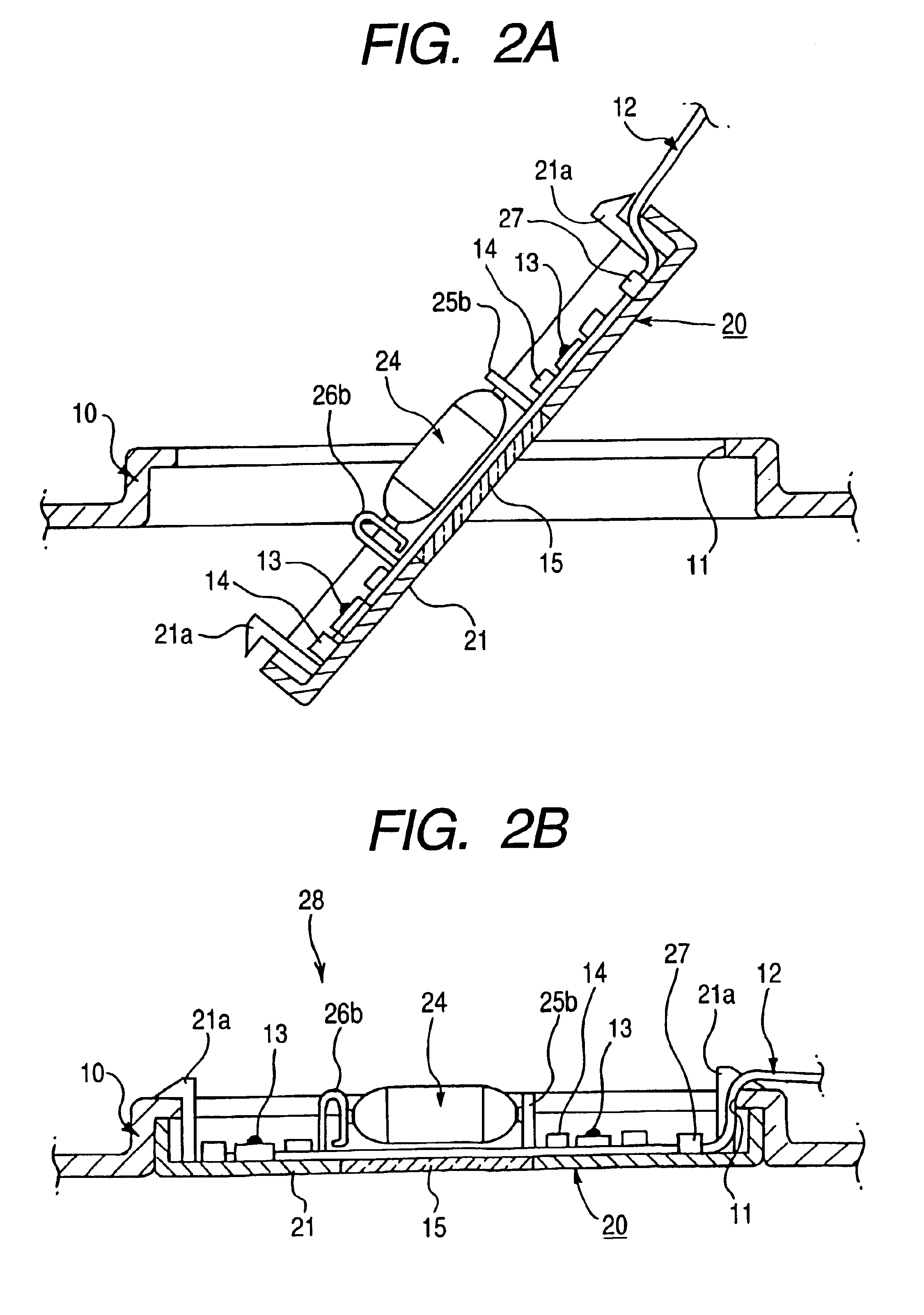
[0086]FIG. 1 is a perspective view illustrating a room lamp to which a lamp unit assembling method according to a first embodiment of the invention is applied. FIGS. 2A and 2B are longitudinal sectional views illustrating a process of mounting the room lamp shown in FIG. 1 onto a roof trim.

[0087]A room lamp 20 of the first embodiment illustrated in FIG. 1 is a lamp unit to be mounted in a lamp mounting window 11 opened in a roof trim 10 serving as an interior wall member covering a body roof (not shown), which is a vehicle body panel. An FFC (flexible flat cable) 12 serving as a cable constituting a roof harness is connected to a bulb 24 mounted in a unit body 21 through a bus bar 25 and a spring terminal 26 (see FIGS. 2A and 2B).

[0088]The unit body 21 has a lens portion 15 corresponding to the bulb 24 placed nearly at the center of a bottom wall portion, and a pair of flexible opposed latching pieces 21a, 21a provided along a pair of opposed side edges, respectively...

Example

Second Embodiment

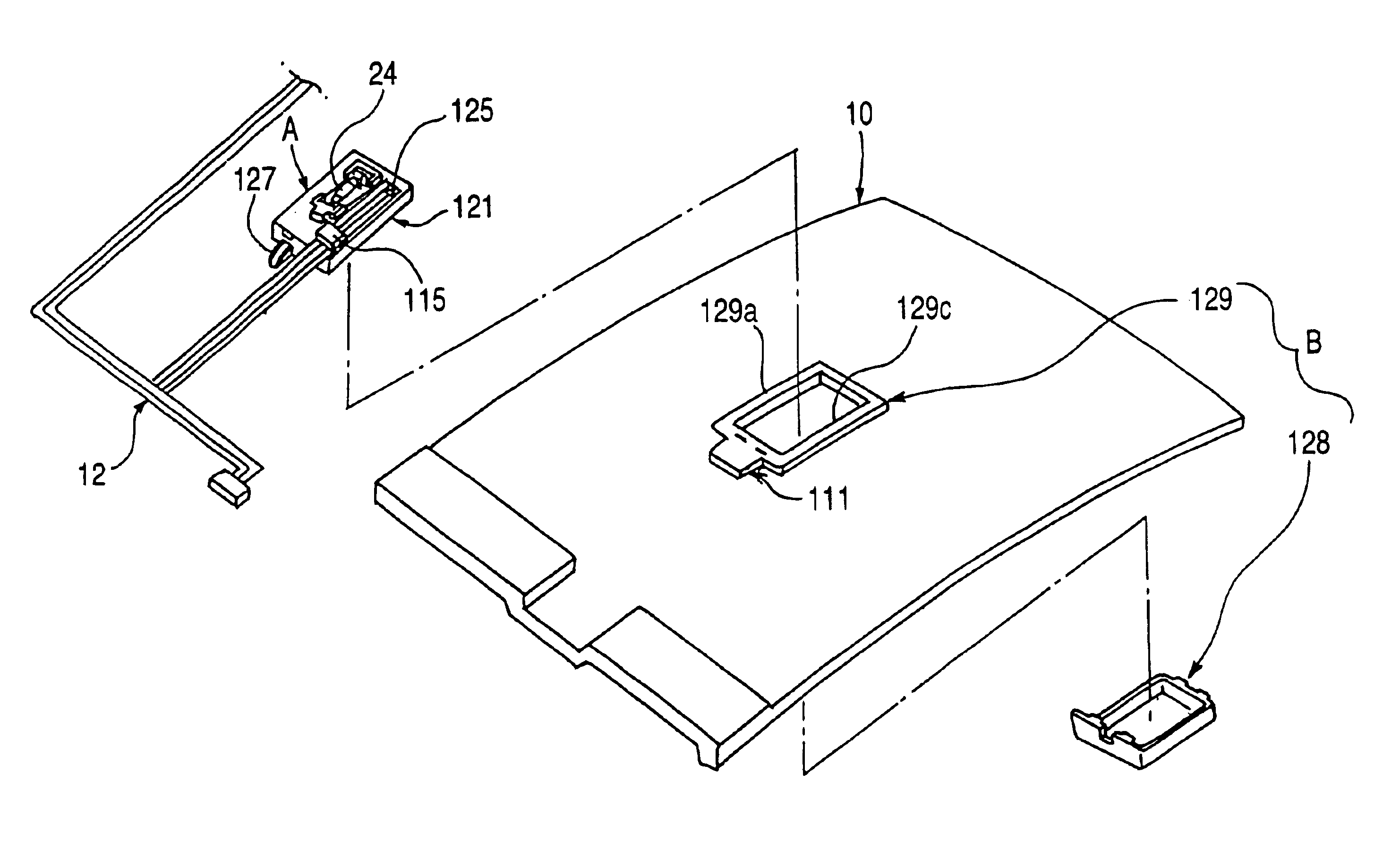
[0101]FIG. 3 is an exploded perspective view illustrating the room lamp to which the lamp unit mounting structure according to the second embodiment of the invention is applied. FIG. 4 is a longitudinal sectional view illustrating a process of mounting the room lamp shown in FIG. 3 onto the roof trim.

[0102]The room lamp 120 of the second embodiment illustrated in FIG. 3 is a lamp unit that is mounted in the lamp mounting window 111 opened in the roof trim 10 serving as the interior wall member covering the body roof (not shown), which serves as the vehicle body panel (see FIG. 4).

[0103]The room lamp 120 comprises a functional portion A and a design portion B. The functional portion A includes a bulb 24 mounted correspondingly to an opening 121b provided in a housing 121, a tab terminal 122 and a spring terminal 123 which serve as bulb contacts, a switch connecting portion 126, and a switch lever 127. The functional portion A is mounted onto a vehicle body panel side...

Example

Third Embodiment

[0123]FIG. 5 is a longitudinal sectional view illustrating a process of mounting a room lamp to which a lamp unit mounting structure according to a third embodiment of the invention is applied.

[0124]A room lamp 140, to which the lamp unit mounting structure according to the third embodiment of the invention is applied, comprises a functional portion A and a design portion B. The functional portion A includes a bulb 24 mounted in an opening provided in a housing 141, a tab terminal 122 and a spring terminal 123. The functional portion A is mounted in a lamp mounting window 111 of the roof trim 10. The design portion B is a cover lens 142 and mounted from the vehicle interior side onto the housing 141 of the roof trim 10. Incidentally, constituent members nearly similar to those of the room lamp 120 of the second embodiment are designated by like reference characters that denote the similar members of the second embodiment. Thus, the detail description of such constitu...


PUM


Abstract

A connection portion (13) of an FFC (12) to be preliminarily arranged on a roof trim (10) is weld-fixed to cable connecting portions (25a, 26a) of a bus bar (25) and a spring terminal (26) of a room lamp (20). Simultaneously with the arrangement of the FFC (12) on a vehicle-body-panel-side portion of the roof trim, the room lamp (20) is mounted in the lamp mounting window.

Description

[0001]This is a divisional of application Ser. No. 09 / 964,609 filed Sep. 28, 2001 U.S. Pat. No. 6,595,668; the disclosure of which is incorporated herein by reference.BACKGROUND OF THE INVENTION[0002]The present invention relates to a lamp unit assembling method and a lamp unit mounting structure for mounting a lamp unit, such as a room lamp, in a lamp mounting window of an interior wall member, such as a roof trim, which covers a vehicle body panel.[0003]Generally, when lamp units, such as a room lamp and a courtesy lamp, are mounted on interior wall members, such as a roof trim and a door trim, each of the lamp units is mounted in a corresponding one of lamp mounting windows opened in the interior wall members.[0004]FIGS. 23 and 24 are a perspective view and a sectional view illustrating a related automobile roof assembling method disclosed in Japanese Unexamined Utility Model Publication Hei. 4-57454 and a related lamp unit assembling structure disclosed in Japanese Unexamined Pa...

Claims


Application Information

Patent Timeline
IPC IPC(8): B60Q3/02B60Q3/00
CPCB60Q3/0296B60Q3/0203B60Q3/82B60Q3/51
Inventor HATAGISHI, YUJIOKABE, TOSHIAKINAGAI, KENTAROOISHI, KENJISHIRAKI, KAZUYUKIYONEYAMA, ISAOTAKAHASHI, GORO
Owner YAZAKI CORP
Why Eureka
Try Eureka