
Method and device for establishing communication links and detecting interference between mobile nodes in a communication system

Inactive Publication Date: 2005-05-31
STINGRAY IP SOLUTIONS LLC
View PDF13 Cites 289 Cited by
  • Summary
  • Abstract
  • Description
  • Claims
  • Application Information

AI Technical Summary

Benefits of technology

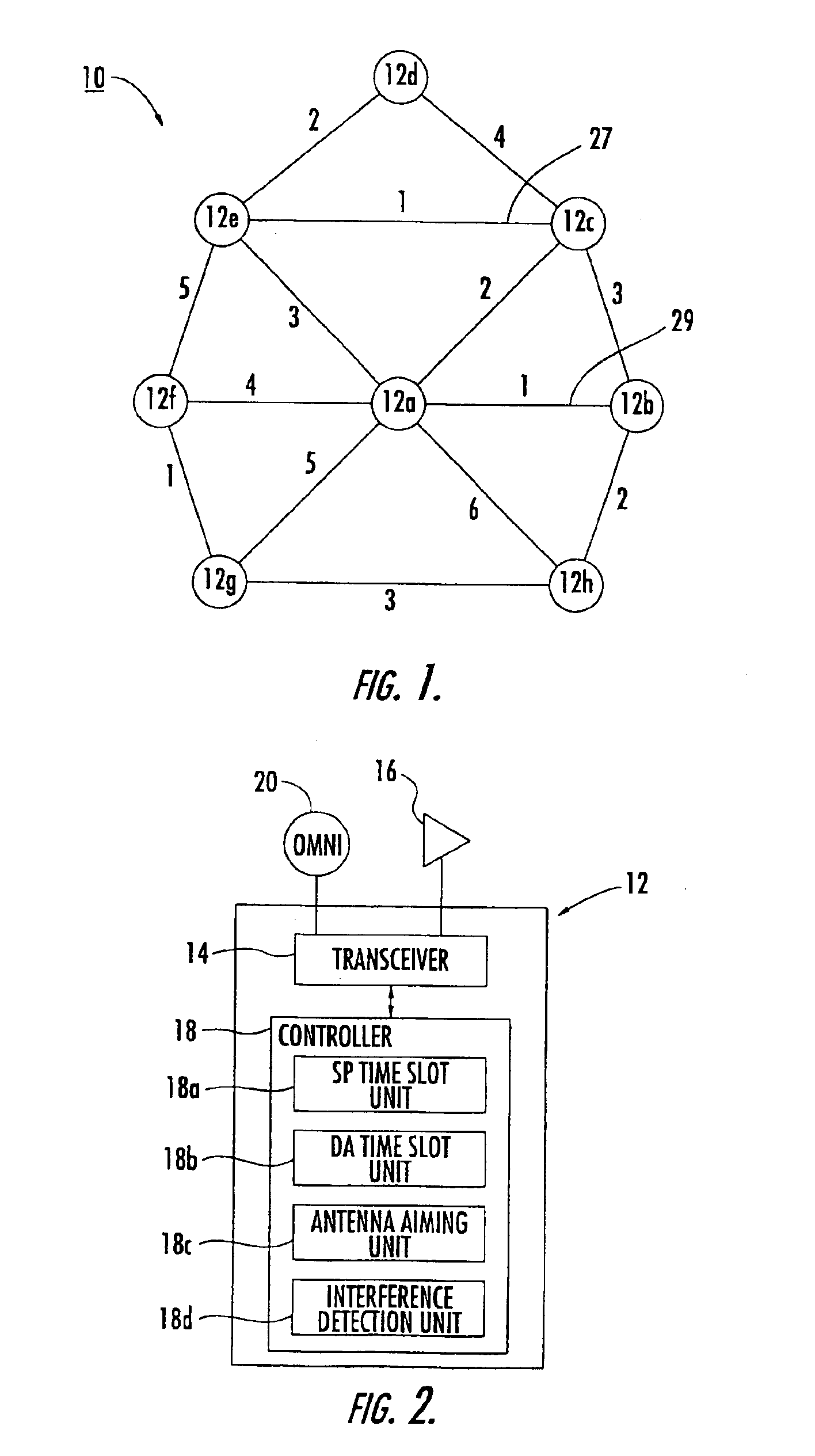
[0011]This and other objects, advantages and features in accordance with the present invention are provided by a wireless communication network including a plurality of mobile nodes each having a transceiver, a directional antenna, e.g. a phased array antenna, connected to the transceiver, and a controller connected to the transceiver. The controller includes a time slot scheduling unit to schedule time slots to establish a communication link with each neighboring mobile node, an antenna aiming unit to aim the directional antenna toward each neighboring mobile node during communication therewith, and an interference detection unit to detect interference in time slots for communication with neighboring mobile nodes. The controller coordinates the scheduling of time slots based upon detected interference. The time slot scheduling unit may include a first time slot unit to schedule a respective semi-permanent time slot for each time frame to establish a communication link with each neighboring mobile node and leaving at least one available time slot in each time frame, and a second time slot unit to schedule the at least one available time slot to also serve the communication link with a neighboring mobile node based upon link communications demand.

Problems solved by technology

The packet error rate may be based upon cyclic redundancy check (CRC) failures.

Method used


Image

  • Method and device for establishing communication links and detecting interference between mobile nodes in a communication system
  • Method and device for establishing communication links and detecting interference between mobile nodes in a communication system
  • Method and device for establishing communication links and detecting interference between mobile nodes in a communication system

Examples


Embodiment Construction

[0024]The present invention will now be described more fully hereinafter with reference to the accompanying drawings in which preferred embodiments of the invention are shown. This invention may, however, be embodied in many different forms and should not be construed as limited to the embodiments set forth herein. Rather, these embodiments are provided so that this disclosure will be thorough and complete, and will fully convey the scope of the invention to those skilled in the art. Like numbers refer to like elements throughout and prime notations are used in alternate embodiments. The dimensions of layers and regions may be exaggerated in the figures for greater clarity.

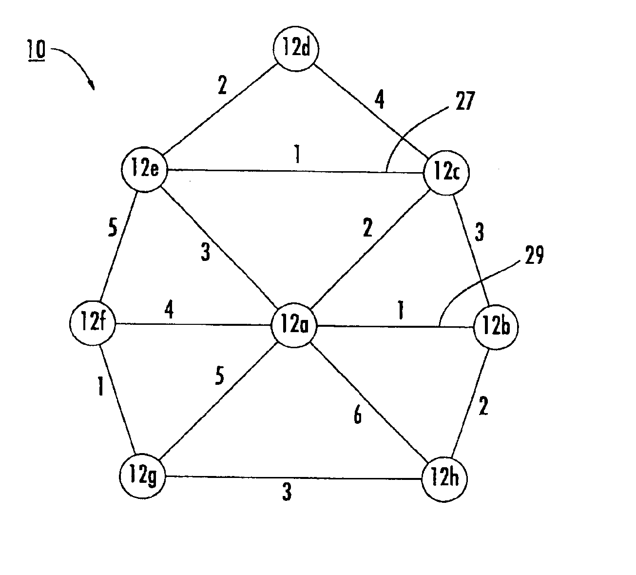
[0025]Referring initially to FIGS. 1-2, a wireless mobile communication network 10 comprises a plurality of wireless mobile nodes 12a-12h. Each mobile node 12a-12h comprises a transceiver 14, a directional antenna 16 connected to the transceiver, and a controller 18 connected to the transceiver.

[0026]The controlle...


PUM


Abstract

A wireless communication network includes a plurality of mobile nodes each including a transceiver, a phased array antenna connected to the transceiver, and a controller connected to the transceiver. The controller schedules a respective semi-permanent time slot for each time frame to establish a communication link with each neighboring mobile node and leaves at least one available time slot in each time frame. The controller also schedules the at least one available time slot to also serve the communication link with a neighboring mobile node based upon link communications demand. The phased array antenna is aimed by the controller towards each neighboring mobile node during communication therewith. The controller also detects interference in time slots for communication with neighboring mobile nodes and coordinates the scheduling of time slots based upon detected interference.

Description

RELATED APPLICATION[0001]This application is a continuation-in-part of copending application Ser. No. 10 / 043,457 filed Jan. 10, 2002, the entire disclosure of which is incorporated herein by reference.[0002]This invention was made with Government support under Contract Number N00014-96-C-2063 awarded by the Naval Research Laboratory. The Government has certain rights in this invention.FIELD OF THE INVENTION[0003]The present invention relates to the field of communications, and more particularly, to a network of mobile communication systems operating with directional antennas.BACKGROUND OF THE INVENTION[0004]Time division multiple access (TDMA) is one example of an access scheme used for establishing communication links between wireless mobile communication systems. Communication links between the wireless mobile communication systems are established within a series of time frames. Each time frame is divided into time slots, with each wireless mobile communication system being assign...

Claims


Application Information

Patent Timeline
IPC IPC(8): H04J3/16H04L1/00H04B7/26H04B7/04H04L1/20H04L12/56H04L12/28H04Q7/36H04W16/14H04W16/28H04W72/10H04W72/12H04W74/04H04W76/02H04W84/18
CPCH04B7/0408H04L1/203H04B7/2643H04J3/1694H04L1/0041H04L1/0061H04W72/085H04W72/1231H04B7/0491H04W24/00H04W40/06H04W72/0446H04W72/10H04W74/04H04W76/02H04W84/18H04W76/10H04W72/542H04W72/56H04B7/26H04B7/04H04W72/12
Inventor CAIN, JOSEPH BIBBBILLHARTZ, THOMAS JAY
Owner STINGRAY IP SOLUTIONS LLC
Learn More