Stack-type diode laser device

a laser device and diode technology, applied in the direction of semiconductor laser structure details, semiconductor laser arrangement, semiconductor lasers, etc., can solve the problems of low output power, difficult fabrication process, and low power of mode diode lasers, and achieve fast tuning speed, wide tuning range, and high power

Inactive Publication Date: 2005-05-31
LI CHIAN CHIU
View PDF9 Cites 28 Cited by
  • Summary
  • Abstract
  • Description
  • Claims
  • Application Information

AI Technical Summary

Problems solved by technology

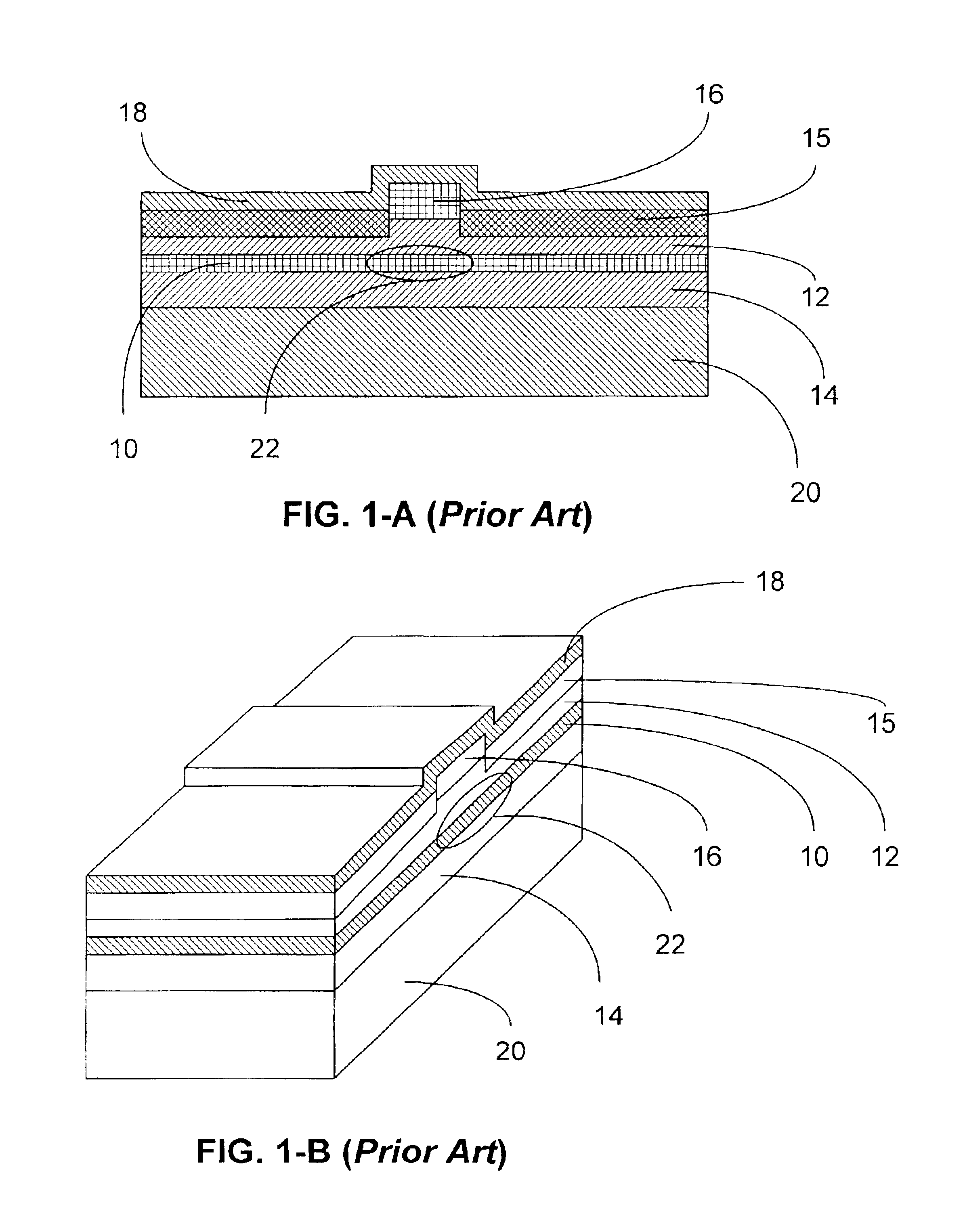
However one of the weaknesses of single-mode diode lasers is that they have relatively low output power.
Its fabrication process is difficult and its yield is low.
This type of diode array suffers from low power due to transverse carrier injection and leakage.
The method is not practical for most fiberoptic telecommunication or optical storage applications due to its complex structure.
Accordingly, all of the above diode array devices suffer from a number of disadvantages, including fabrication difficulties, low output power, and complex structures.
Thus the system becomes clumsy and its cost is more than doubled.
The cost increase results from the added parts and the additional packaging processes, where the latter cost is much higher in a diode laser assembly.
Accordingly, a dual-wavelength dual-module fiber-pigtailed system is clumsy and not cost-effective.
Among various tunable lasers, distributed feedback (DFB) lasers offer high power, but suffer a narrow tuning range and a slow tuning speed.
Sampled grating DBR (SG-DBR) lasers and superstructure grating DBR (SSG-DBR) lasers have a wide tuning range and a fast tuning speed, but low output power.
Conventional tunable external cavity diode lasers benefit from high power and a wide tuning range, but suffer a slow tuning speed.
Accordingly, the above tunable lasers can't satisfy the three specifications: high power, wide tuning range, and fast tuning speed.
A single output beam has a coupling loss when coupled to a single- mode fiber directly or by a focus lens.
If two output beams are coupled to the single-mode fiber, each beam is intentionally misaligned a bit and bears additional coupling loss besides the original one.
When a focus lens is used to magnify the beam mode size, the original coupling loss is reduced, but the additional coupling loss is increased.
Besides the additional coupling loss, stability of coupled power becomes an issue due to the steep curve of coupling loss versus fiber position deviation.
For wavelengths shorter than 1.55 microns, coupling loss issues become even worse.
They can't share a fiberoptic system designed for a single diode.

Method used


Image

  • Stack-type diode laser device
  • Stack-type diode laser device
  • Stack-type diode laser device

Examples


first embodiment

[0081]In a first embodiment the reflection spectrum contains a single narrow band. The narrow reflection band helps generate an output having a narrow spectral width. Coupling two DBR diodes with substantially close reflection bands increases the output power while maintaining its narrow spectral width.

[0082]The output power is further increased if one is a DBR diode and the other is a gain chip as shown schematically in FIG. 4-C. The stack-type device comprises a three-section DBR diode 62, and a gain chip 52 with a HR coating 42 on its rear facet and an AR coating 40 on its front facet. In the DBR hybrid design, the gain chip serves as a broadband optical amplifier and lases at the working wavelength of the DBR diode. The DBR hybrid design generates higher output power at a lower cost than a design of two DBR diodes.

[0083]If the two DBR diodes or the DBR diode in hybrid design are tunable, the stack-type device becomes a tunable DBR diode laser. The Bragg reflector determines the ...

second embodiment

[0084]In a second embodiment the Bragg reflectors have comb-like reflection spectra.

[0085]Returning to FIG. 4-B, Bragg reflectors 6 and 56 now provide a high reflection for two groups of wavelengths. Their reflection spectra look like a comb. The two comb-like spectra have different free spectral ranges, or peak-to-peak spacings. The embodiment works as a tunable external cavity DBR diode laser. Based on the Vernier effect, lasing occurs at a wavelength where two peaks of the two comb-like spectra coincide. Like SG-DBR and SSG-DBR lasers, wavelength tuning is accomplished by tuning the two comb-like spectra so that two peaks coincide at different desired wavelengths. Although the comb-like spectra have a narrow tuning range of several nanometers, their peaks can coincide in a much wider range. The tunable external cavity DBR diode laser has a tuning range of about 40 nanometers. The tuning speed is fast, i.e. the output wavelength can be tuned within its tuning range in several nano...


PUM


Abstract

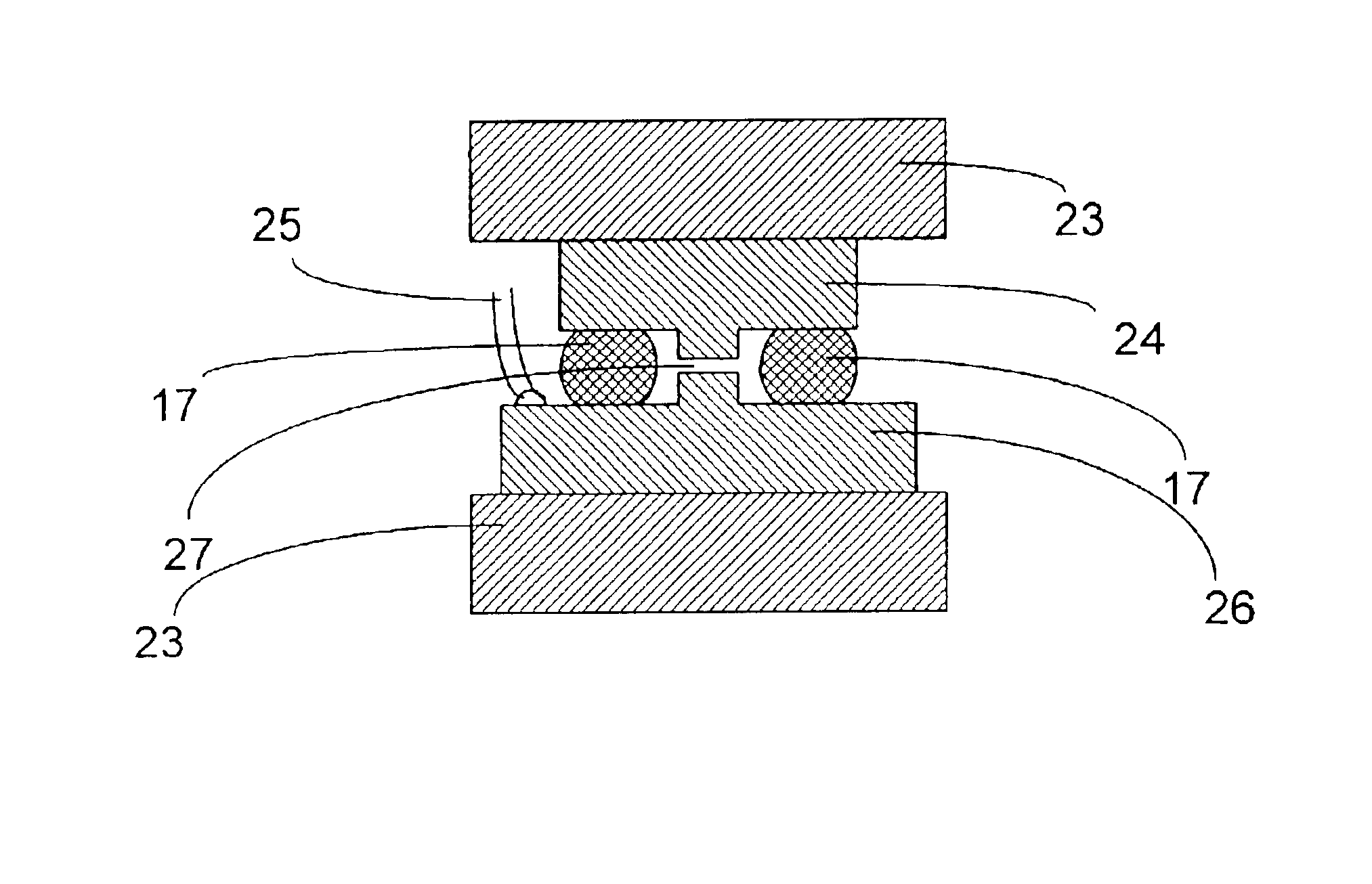
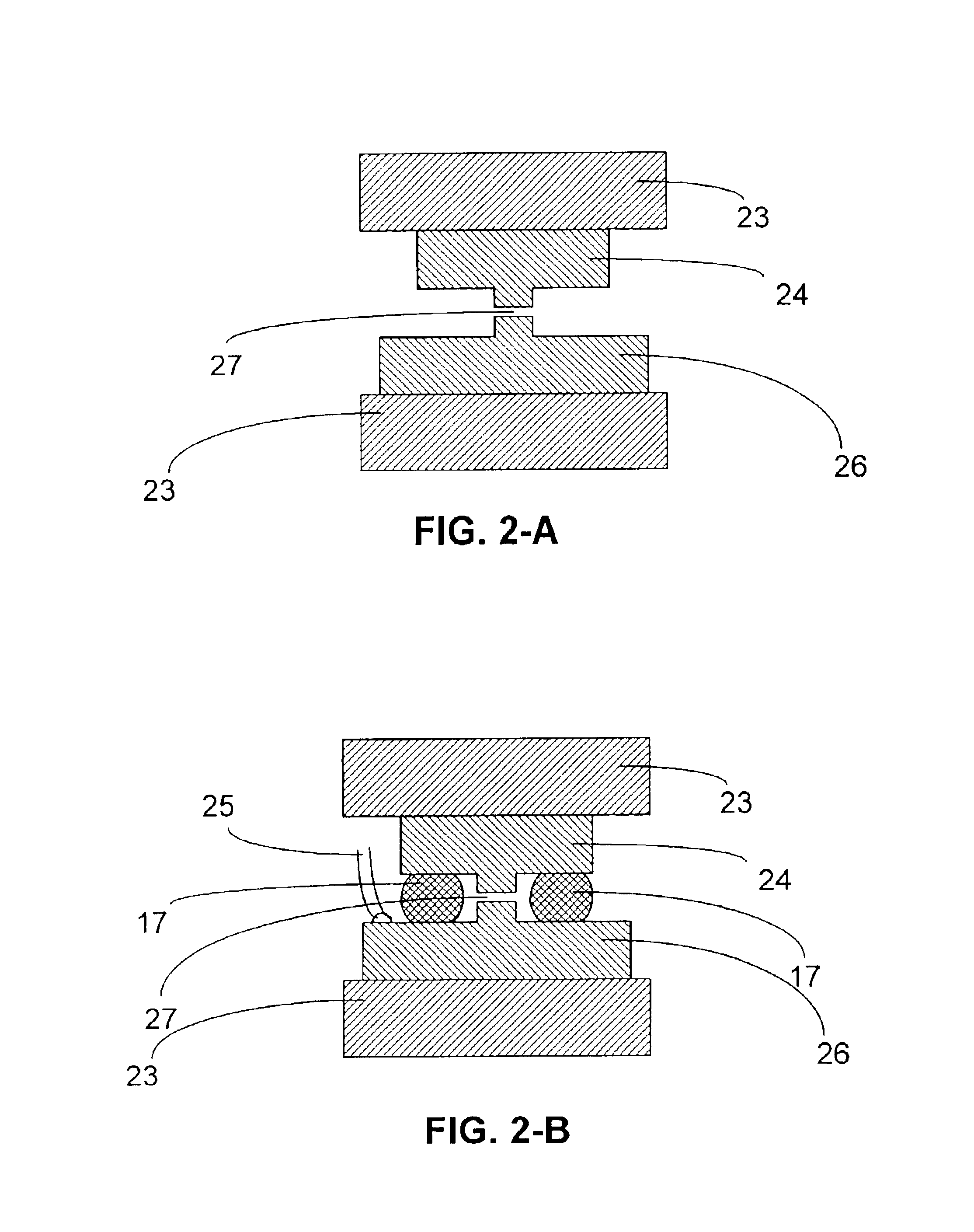
Two thin-clad laser diodes are disposed to form a stack-type device that emits two beams. The beams are substantially parallel and in proximity such that they share many fiberoptic systems designed for a single beam. In one embodiment the device functions as a dual-wavelength fiber-pigtailed light source. In another embodiment a feedback mechanism is provided to couple the diodes. Other embodiments include structures and methods for output power enhancement and tunable lasers.

Description

FEDERALLY SPONSORED RESEARCH[0001]Not applicableSEQUENCE LISTING OR PROGRAM[0002]Not applicableBACKGROUND—FIELD OF INVENTION[0003]This invention relates to semiconductor lasers, and particularly to stack-type semiconductor laser devices.BACKGROUND—DESCRIPTION OF PRIOR ART[0004]As used here, the term “semiconductor laser” or “diode laser” means edge-emitting diode lasers. Edge-emitting diode lasers have a horizontal cavity and emit light beams in a direction parallel to the wafer's plane or an active region of the wafer. Most semiconductor lasers in use are edge-emitting and are used for laser printers, fiberoptic telecommunication systems, and optical data storage devices.[0005]A diode emits an output light beam with a spatial power distribution. The output of a single transverse mode, or a single mode diode, has a single lobe in its spatial power distribution, while a multimode output diode has multiple lobes. Single-mode diode lasers are desirable in many fields, especially in fib...

Claims


Application Information

Patent Timeline
Patent Type & Authority Patents(United States)
IPC IPC(8): H01S5/00H01S5/022H01S5/40H01S5/02
CPCH01S5/0224H01S5/02272H01S5/4087H01S5/4043H01S5/02284H01L2224/16145H01L2224/48463H01S5/02251H01S5/0234H01S5/0237
Inventor LI, CHIAN CHIU
Owner LI CHIAN CHIU
Why Eureka
Try Eureka