Process for operation of a burner with controlled axial central air mass flow

a central air mass flow and burner technology, applied in the field of burners, can solve the problems of affecting the operation of the burner, the recirculation zone can detach from the burner outlet, and the burner can be overheated gradually, and the danger of flashback flames, etc., to achieve stable and free from pulsation, prevent acoustic resonance in the combustion chamber, and low pollution

Inactive Publication Date: 2005-06-07
ANSALDO ENERGIA SWITZERLAND AG
View PDF36 Cites 100 Cited by
  • Summary
  • Abstract
  • Description
  • Claims
  • Application Information

AI Technical Summary

Benefits of technology

[0012]An aspect of the invention is thus to provide the burner with a variable geometry of the central injection. It is possible in this manner to match the axial impulse of the central flow to the operating conditions at any given time. This makes it possible to affect the position and intensity of the recirculation zone in a targeted manner. It is thereby possible in a particularly advantageous manner to reduce the amount of air introduced centrally at a low burner load, such that the recirculation zone forms very near to the burner mouth or even partially within the burner interior, so that a superior flame stability results. At high load and high flame temperatures, in contrast, high stability is already intrinsically inherent in the flame. Here the centrally introduced amount of air can be increased such that the recirculation zone comes to be reliably situated a distance downstream of the burner mouth. Thermal overloading of the burner is thereby prevented.
[0016]A further operating method results with advantageous operation in the combustion chamber in gas turbines. Here the variable central geometry in combination with the operating concepts of gas turbines with premixers, which are familiar to the skilled person, furthermore serves to ensure operation which is low in pollutants and at the same time stable and free from pulsation. Finally, a variation of the conditions can be set for individual burners in a targeted manner, in order to prevent acoustic resonances in the combustion chamber by a detuning of individual burners.

Problems solved by technology

The danger then exists of a flashback of the flame and a gradual overheating of the burner.
If, on the other hand, the axial flow is too strong, the recirculation zone can detach from the burner outlet and become unstable.
The consequence can be strong, damaging, combustion pulsations or even an extinction of the flame.
Solutions known from the state of the art are not capable of setting an optimum axial position of the recirculation zone under all operating conditions.

Method used


Image

  • Process for operation of a burner with controlled axial central air mass flow
  • Process for operation of a burner with controlled axial central air mass flow
  • Process for operation of a burner with controlled axial central air mass flow

Examples


first embodiment

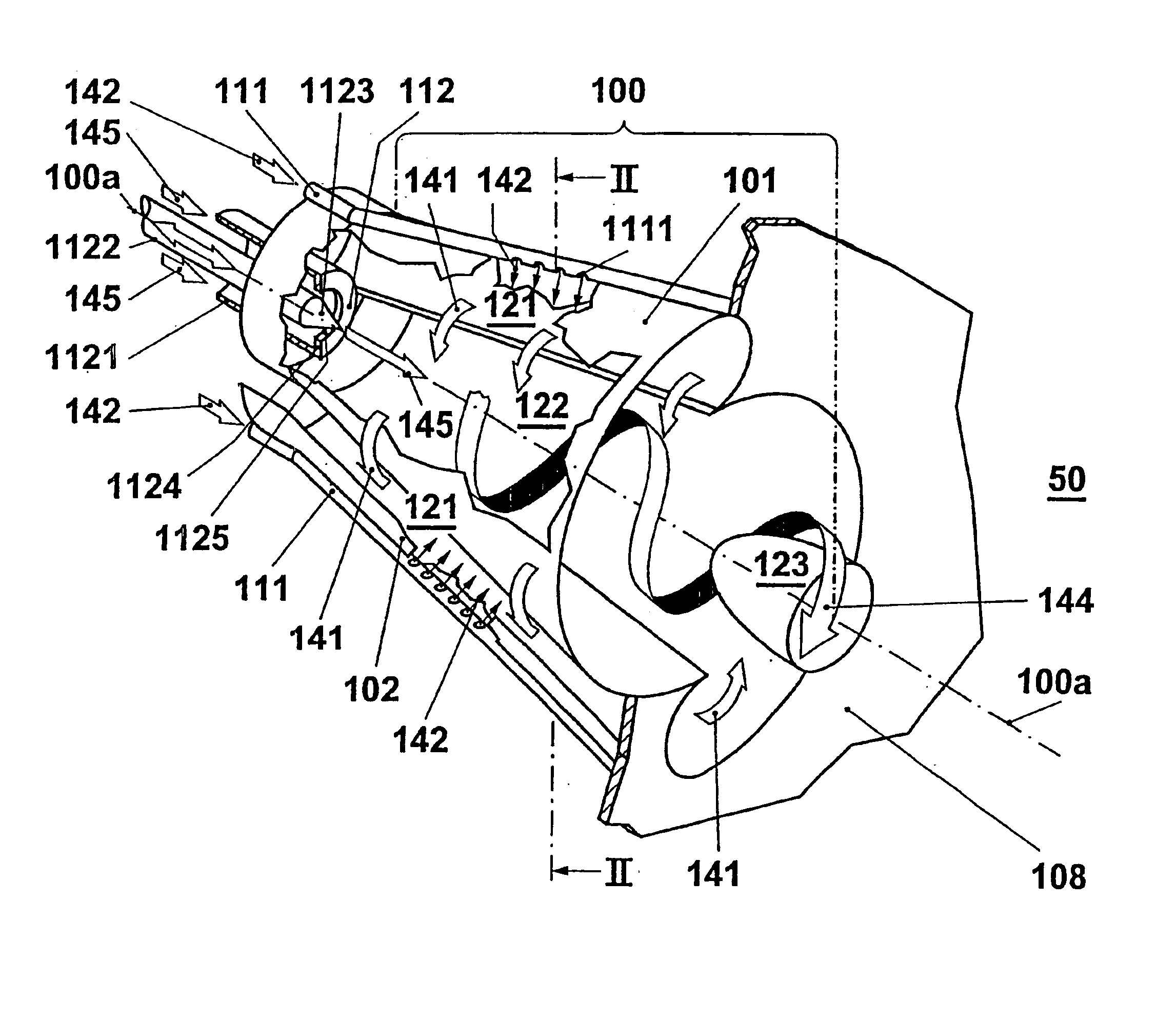
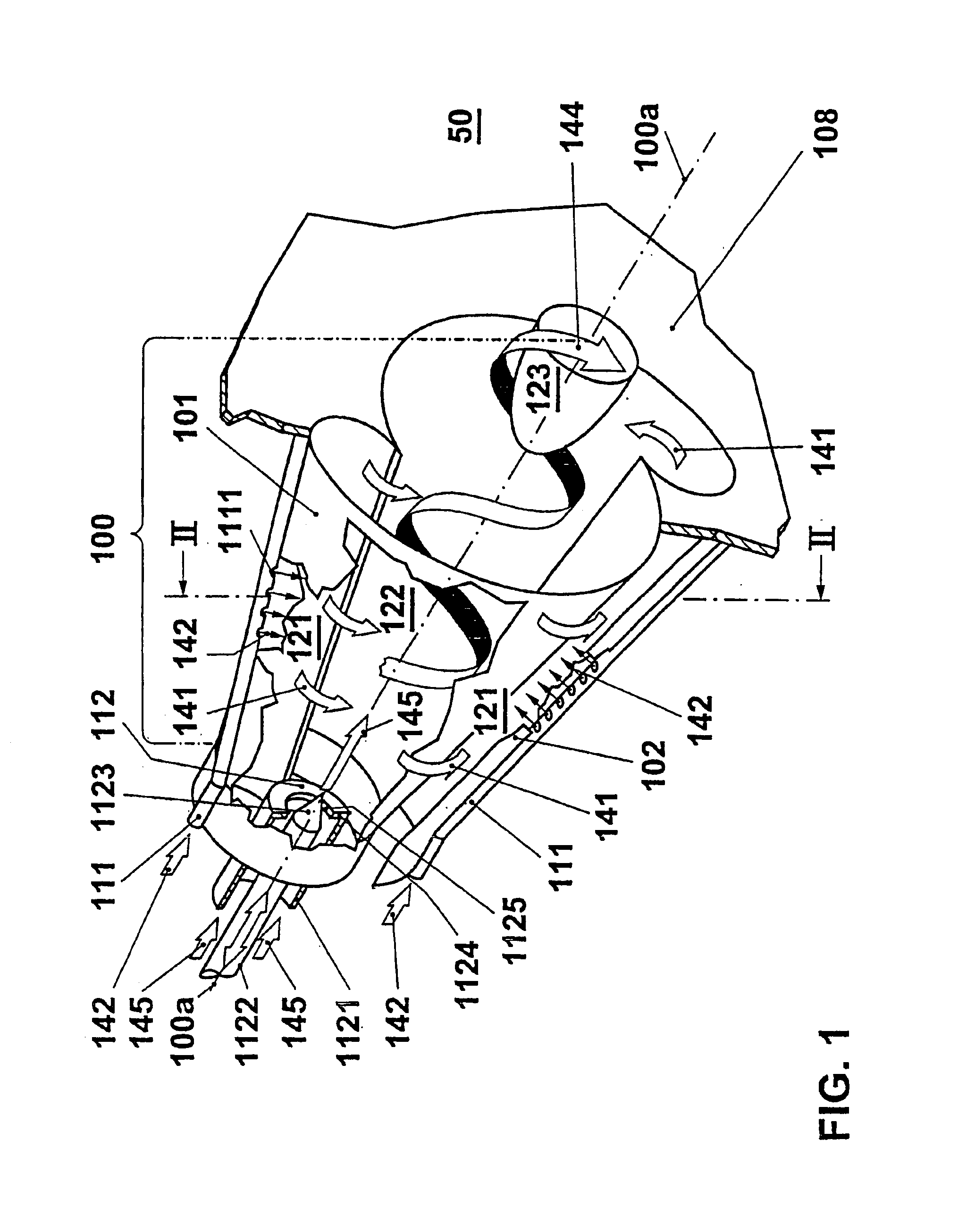
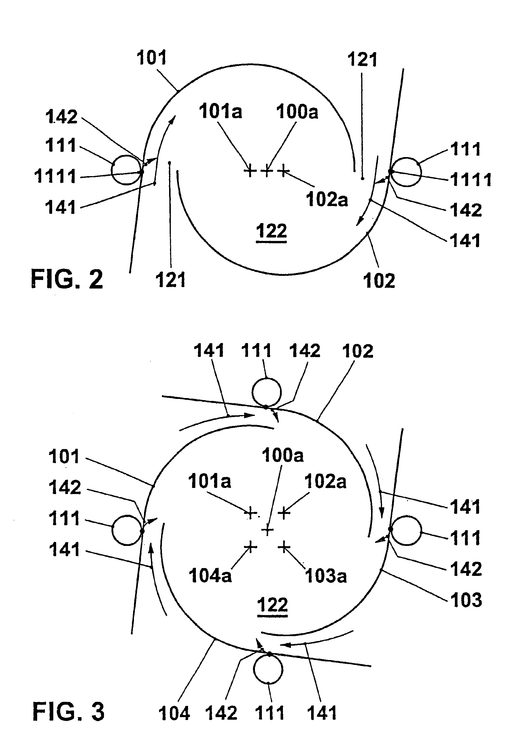
[0054]Burners are likewise known from WO 93 / 17279 and EP 0 945 677, and have cylindrical swirl generators with tangential combustion air inlets. In this connection it is also known to arrange a displacement member, tapering toward the burner mouth, in the interior of a cylindrical swirl generator. The favorable criterion given above for the axial throughflow cross section of the swirl generator, namely that the axial throughflow cross section increases in the axial throughflow direction, is fulfilled by means of such a swirl generator internal member. Embodiments of such burners are shown in FIGS. 9 and 10. The first embodiment in FIG. 9 shows the principle of such a burner. The mode of operation is sufficiently known and explained in principle in connection with FIG. 1; deviating from the embodiment shown in FIG. 1 of a burner according to the invention, the embodiment shown in FIG. 9 of course has a conical compression member which tapers in the combustion space 50 toward the burn...

second embodiment

[0062]A second embodiment, shown in FIG. 15, concerns the use of the burner according to the invention in gas turbine plants, for which the burner according to the invention is especially suitable. In the example in FIG. 15, a compressor 10, a turbine 30, and a generator 40 are arranged on a common shaft. The compressor 10 is equipped with an adjustable front guide vane set 11. A combustion chamber 20 is arranged in the flow path of a working medium, between the compressor 10 and the turbine 30. The combustion chamber 20 is operated with at least one burner 1 according to the invention. A regulating signal Y is passed from a control unit 3 to the adjustable device for the injection of the axial central flow. In the example shown, the control unit 3 receives a power signal XP, signals XAMB from sensors (not shown) which determine ambient conditions—temperature, moisture, pressure, etc.—of the ambient air, and also a signal XVLE which reproduces the position of the front guide vane se...


PUM


Abstract

An aerodynamically stabilized premixing burner includes a swirl generator for the production of a rotating combustion air flow, and a device for the introduction of at least one fuel into this combustion air flow. The burner is advantageously provided with a device for the introduction of an axial air flow into the center of the generated rotational flow. This axial air flow is controllable in order to affect the position and intensity of the flame-stabilizing recirculation zone at the burner mouth.

Description

[0001]This application is related and claims priority under 35 U.S.C. § 119 to German Patent Application No. 100 50 248.2, filed Oct. 11, 2000, the entire contents of which are incorporated by reference herein. In addition, this application is a divisional of U.S. patent application Ser. No. 09 / 973,868 filed on Oct. 11, 2001, now abandoned, the entire contents of which are incorporated by reference herein.FIELD OF THE INVENTION[0002]The invention relates to a burner for a heat generator.BACKGROUND OF THE INVENTION[0003]From EP 0 321 809 (US equivalent U.S. Pat. No. 4,932,861), EP 0 780 629 (US equivalent U.S. Pat. No. 5,735,687), WO 93 / 17279 (US equivalent U.S. Pat. No. 5,402,633), and EP 0 945 677 (US equivalent U.S. Pat. No. 6,178,752), premixing burners are known in which a combustion air flow is introduced tangentially into a burner interior by means of a swirl generator and is mixed with fuel. At the burner outlet, the resulting vortex flow bursts open at a jump in cross sectio...

Claims


Application Information

Patent Timeline
Patent Type & Authority Patents(United States)
IPC IPC(8): F23D14/02F23C7/00
CPCF23C7/002F23C7/008F23D14/02F23R2900/00014F23R2900/00013F23C2900/07002
Inventor DITTMANN, ROLFSTEINBACH, CHRISTIAN
Owner ANSALDO ENERGIA SWITZERLAND AG
Why Eureka
Try Eureka