Chuck device

a chuck and chuck technology, applied in the direction of chucks, mechanical devices, manufacturing tools, etc., can solve the problems of loosening mechanism and process failure, and achieve the effects of enhancing claw sliding movement, reducing friction coefficient, and demonstrating good gripping for

Inactive Publication Date: 2005-06-07
YUKIWA SEIKO
View PDF15 Cites 25 Cited by
  • Summary
  • Abstract
  • Description
  • Claims
  • Application Information

AI Technical Summary

Benefits of technology

[0017]In the chuck device according to the present invention, the coating that is hard and has a low friction coefficient as much as possible is applied to the inner surface of the hole through which the claws are slidingly moved whereby the sliding movement of the claws are enhanced and correspondingly thereto, the grip force of the tool is exhibited well.
[0018]Since the present invention is thus summarized, it is possible to provide the chuck device that may grip the tool well.

Problems solved by technology

However, in the case where the body is made of light alloy such as aluminum, there is no problem such as rust and hence the plating process is unnecessary.
However, studying various aspects, it has been confirmed that, even if the body is made of light alloy such as aluminum, unless the plating process is performed, the ratchet teeth of the ratchet wheel are worn due to repeated and continuous engagement between the retainer spring made of steel and the ratchet teeth, so that the loosening preventing mechanism does not work, disadvantageously.

Method used


Image

  • Chuck device
  • Chuck device
  • Chuck device

Examples


first embodiment

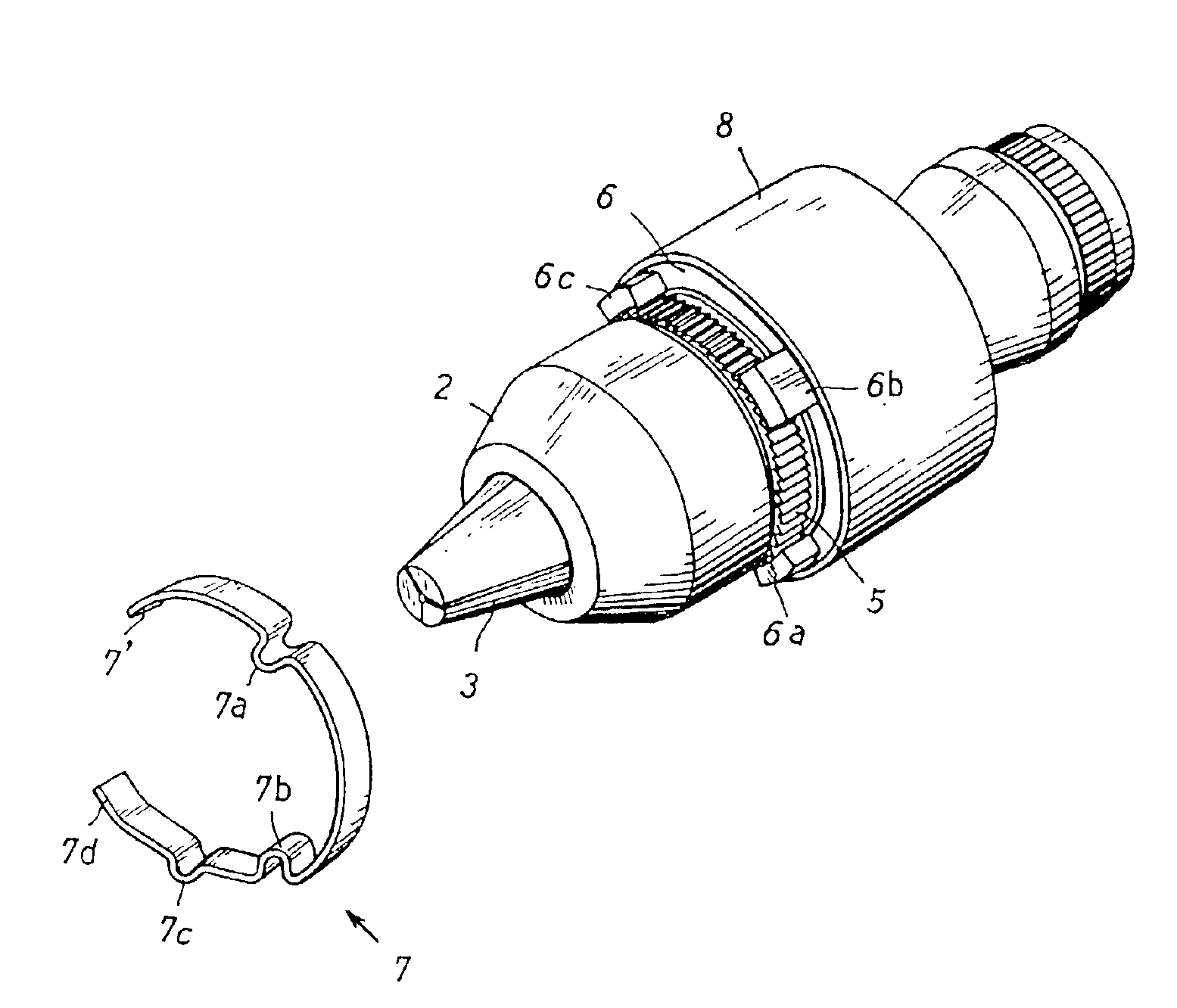
[0055]Also, in the chuck device since the body 2 is made of light material, the body is light in weight and superior in practical applicability. Furthermore, since the above-described coating is applied to the surface of the body 2, even if the cut powder is brought into collision with the body 2, the latter is hardly damaged. Moreover, since the above-described coating is applied also to the ratchet teeth 5, the wear of the ratchet teeth 5 is prevented as much as possible. At the same time, the engagement and disengagement with the retainer spring member 7 is smoothly performed. Also, since the above-described coating is applied to the inner surface of the hole 2a of the body 2, the sliding movement of the claws 3 is performed smoothly whereby the grip of the tool 4 is smoothly performed. In particular, with the so-called hummer drill, the vibration drill, the driver drill and the like that is to impart the vibration or the shock, the vibration works in the axial direction or the ...

second embodiment

[0057]FIGS. 5 to 7 show the present invention. This will now be described.

[0058]In the second embodiment, the retainer spring member 7 of the first embodiment is composed of two retainer spring members 30 and 31. One of the retainer spring members 30 functions to retain the ratchet teeth 5 and the other retainer spring member 31 functions to maintain the position of the rotary sleeve 1 to thereby retain the retainer spring member 30 in a predetermined position. Thus, according to the second embodiment, the retention function of the ratchet teeth 5 and the retainer maintenance function and the retention release function of the ratchet teeth 5 are separated to the different springs unlike the first embodiment. The other structure is the same as that of the first embodiment.

[0059]Reference character 30′ denotes a portion corresponding to the tip end retainer portion 7′ of the first embodiment, character 30a denotes a portion corresponding to the projection 7a of the first embodiment, c...


PUM

PropertyMeasurementUnit
thicknessaaaaaaaaaa
frictional coefficientaaaaaaaaaa
weightaaaaaaaaaa

Abstract

To provide a chuck device for preventing the loosening of the fastening condition, a plurality of claws inserted into a hole provided at an end of a body are opened, closed and slid by the rotation of a rotary sleeve and a tool is clamped by means of the claws. A coating that is hard and has a low frictional coefficient as much as possible is applied to an inner surface of the hole.

Description

BACKGROUND OF THE INVENTION[0001]1. Field of the Invention[0002]The present invention relates to a chuck device for clamping a tool.[0003]2. Description of the Related Art[0004]Recently, there is a strong demand of reducing weight for a chuck device. It is proposed to form a body of light alloy such as aluminum. Incidentally, the structure according to the related art is the same as that of a first embodiment of the present invention. Accordingly, the structure of the related art will be described with reference to FIGS. 1 to 4.[0005]For example, a chuck device with a loosening preventing mechanism has been proposed in which a plurality of claws 3 inserted into a hole 2a provided at an end of a body 2 are opened, closed and slid by the rotation of a rotary sleeve 1 and a tool 4 is clamped by means of the claws 3, wherein an annular ratchet wheel 5 is provided on the body 2, an annular nut member 6 to be engaged with the claws 3 and to be rotated together with the rotary sleeve 1 is ...

Claims


Application Information

Patent Timeline
Patent Type & Authority Patents(United States)
IPC IPC(8): B23B31/12C25D11/04
CPCB23B31/123B23B31/1238Y10T279/32Y10S279/902Y10T279/17632B23B2222/04
Inventor SAKAMAKI, KAZUOSAKAMAKI, AKIRASATO, CHOKICHITANIGUCHI, TADASHI
Owner YUKIWA SEIKO
Why Eureka
Try Eureka