High omnidirectional reflector

a high-omnidirectional, reflector technology, applied in the field of photonic crystals, can solve the problems of difficult fabrication of crystals, if designed for infrared or optical light, and achieve the effect of high omnidirectional energy reflection

Inactive Publication Date: 2005-06-07
MASSACHUSETTS INST OF TECH
View PDF44 Cites 81 Cited by
  • Summary
  • Abstract
  • Description
  • Claims
  • Application Information

AI Technical Summary

Benefits of technology

[0006]It is therefore an object of the invention to provide a dielectric structure that acts as a perfect m

Problems solved by technology

These crystals, if designed for infrared or optical light, are difficult to fabri

Method used


Image

  • High omnidirectional reflector
  • High omnidirectional reflector
  • High omnidirectional reflector

Examples


Embodiment Construction

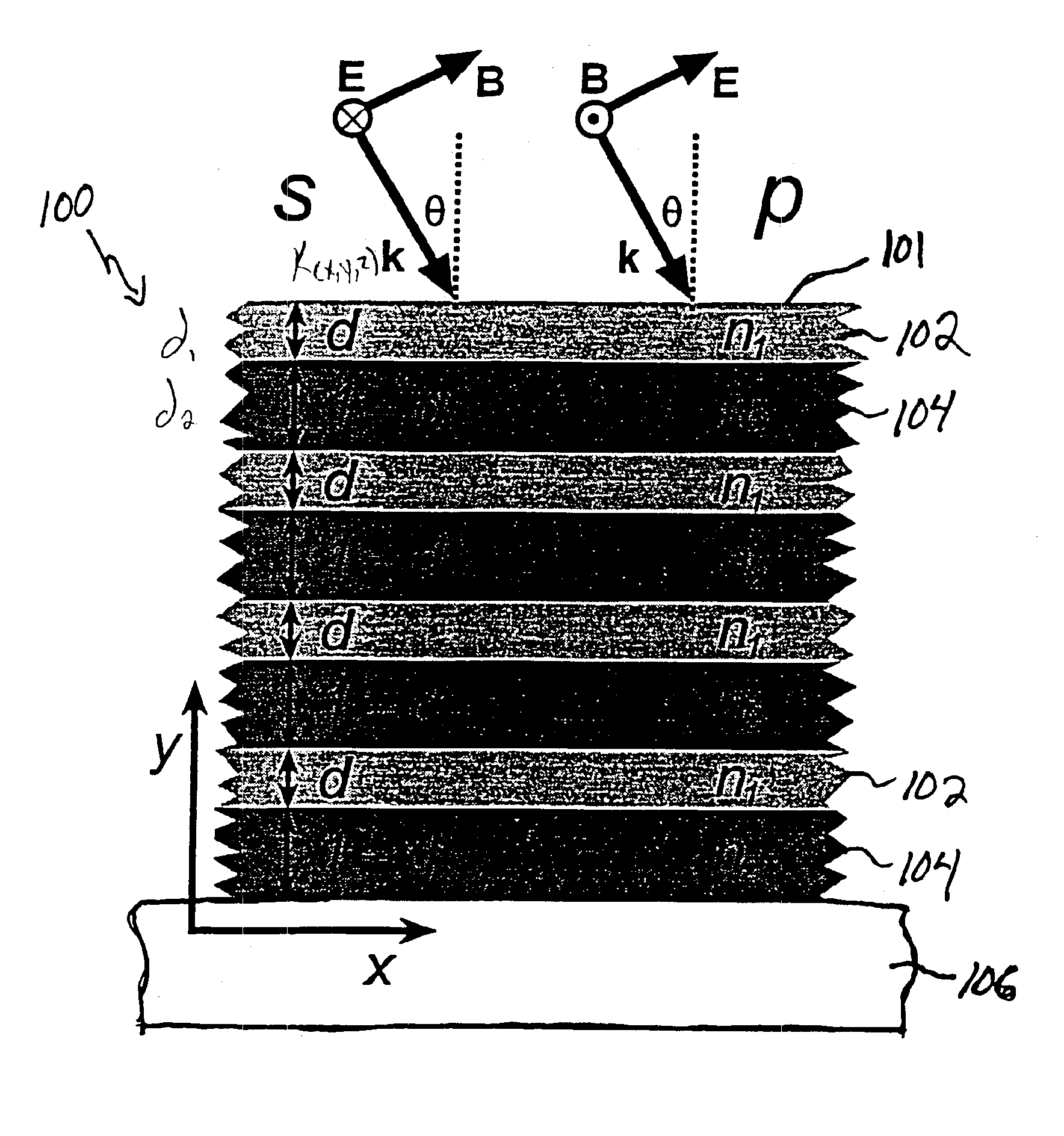
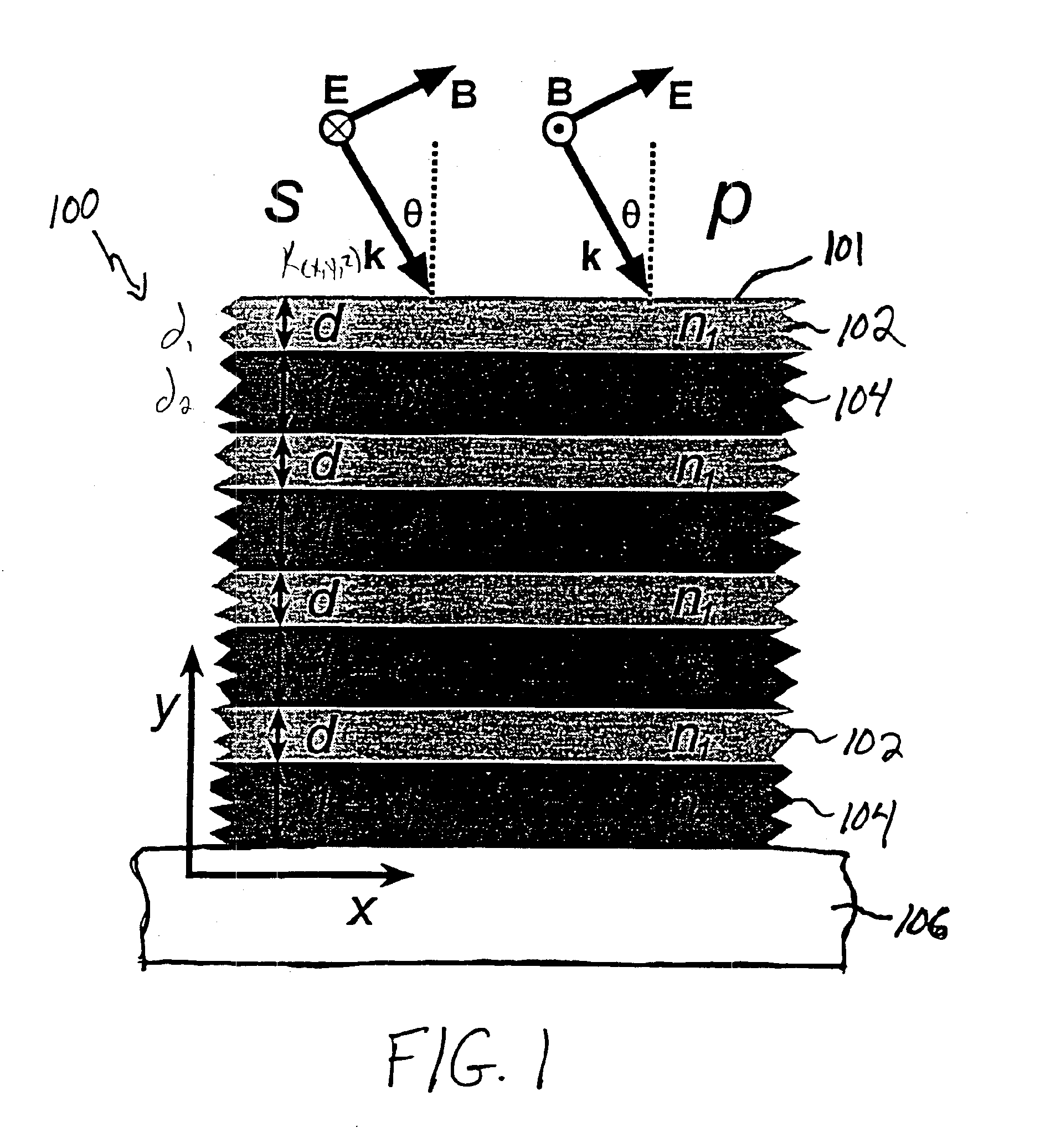
[0015]FIG. 1 is a schematic block diagram of an exemplary embodiment of a high omnidirectional reflector 100 in accordance with the invention. The reflector 100 is a one-dimensionally periodic photonic crystal having an index of refraction that is periodic in the y-coordinate, perpendicular to a surface 101, and consists of a repeating stack of dielectric slabs 102, 104, which alternate in thickness from d1 to d2 (in the illustrated embodiment d2=1−d) and an index of refraction from n1 to n2. In the illustrated embodiment, d1 and d2 are assumed to be in the unit of period a. Only a few periods of such a periodic system are illustrated. For a quarter-wave stack, n1d1=n2d2. The stacks are fabricated in a conventional manner on a substrate 106, e.g., silicon.

[0016]FIG. 1 also shows two orthogonal polarizations of incident light. An s-polarized wave has an electric field E perpendicular to the plane of incidence. A p-polarized wave has an electric field parallel to the plane of incidenc...


PUM


Abstract

A reflector, a method of producing same and a method of creating high omnidirectional reflection for a predetermined range of frequencies of incident electromagnetic energy for any angle of incidence and any polarization. The reflector includes a structure with a surface and a refractive index variation along the direction perpendicular to the surface while remaining nearly uniform along the surface. The structure is configured such that i) a range of frequencies exists defining a photonic band gap for electromagnetic energy incident along the perpendicular direction of said surface, ii) a range of frequencies exists defining a photonic band gap for electromagnetic energy incident along a direction approximately 90° from the perpendicular direction of said surface, and iii) a range of frequencies exists which is common to both of said photonic band gaps. In an exemplary embodiment, the reflector is configured as a photonic crystal.

Description

PRIORITY INFORMATION[0001]This application is a continuation of U.S. Ser. No. 09 / 253,379 filed Feb. 19, 1999, now U.S. Pat. No. 6,130,780, which claims priority from provisional application Ser. No. 60 / 075,223 filed Feb. 19, 1998.SPONSORSHIP INFORMATION[0002]This invention was made with government support under 9400334-DRM awarded by the National Science Foundation. The government has certain rights in the invention.BACKGROUND OF THE INVENTION[0003]The invention relates to the field of photonic crystals, and in particular to a dielectric high omnidirectional reflector.[0004]Low-loss periodic dielectrics, or “photonic crystals”, allow the propagation of electromagnetic energy, e.g., light, to be controlled in otherwise difficult or impossible ways. The existence of photonic bandgap in certain photonic crystals has given rise to the possibility that a photonic crystal can be a perfect mirror for light from any direction, with any polarization, within a specified frequency range. Withi...

Claims


Application Information

Patent Timeline
IPC IPC(8): G02B6/122G02B6/12G02B5/08G02B5/28G02B5/30
CPCB82Y20/00G02B5/0825G02B6/1225G02B27/0012G02B6/122G02B2006/12104
Inventor JOANNOPOULOS, JOHN D.FAN, SHANHUIWINN, JOSHUA N.FINK, YOEL
Owner MASSACHUSETTS INST OF TECH
Why Eureka
Try Eureka