Method and apparatus for machining workpieces

a technology for workpieces and machining methods, applied in the direction of manufacturing tools, transportation and packaging, other manufacturing equipment/tools, etc., can solve the problems of increasing construction costs, requiring the supply of own miscellaneous equipment, and separating lathes with their own control, so as to achieve less construction costs, improve reliability, and simplify the effect of operation

Inactive Publication Date: 2005-06-14
EMAG HLDG GMBH
View PDF17 Cites 19 Cited by
  • Summary
  • Abstract
  • Description
  • Claims
  • Application Information

AI Technical Summary

Benefits of technology

[0009]Consequently, the invention relates to a method and apparatus comprising a machine tool that is designed in such a way that the transport of the workpieces from one machining station to the next machining station can be carried out in a much simpler, more reliable, and less expensive fashion.

Problems solved by technology

One disadvantage of this arrangement can be seen in the fact that a completely separate lathe with its own control, its own drive, and its own miscellaneous equipment must be provided for each machining step that is to be carried out.
Another disadvantage is that a separate rotating / pivoting device needs to be provided for each transfer from one lathe to the next lathe, significantly increases construction expenses.
This device can only be used for machining of very specific workpieces and is particularly unsuitable for any machining of wavy or tubular workpieces.
The gripping element requires its own holding arrangement and its own drive, and frequently obstructs the work region of a machine tool due to the small available space.
In addition, its manufacture is comparatively expensive because the gripping element requires its own holding arrangement and its own drive.
However, the device merely comprises a series of individual elements, in particular gripping elements and a tool turret, but no combination of these elements, so that significant construction expenses and correspondingly high costs result.

Method used


Image

  • Method and apparatus for machining workpieces
  • Method and apparatus for machining workpieces
  • Method and apparatus for machining workpieces

Examples


Embodiment Construction

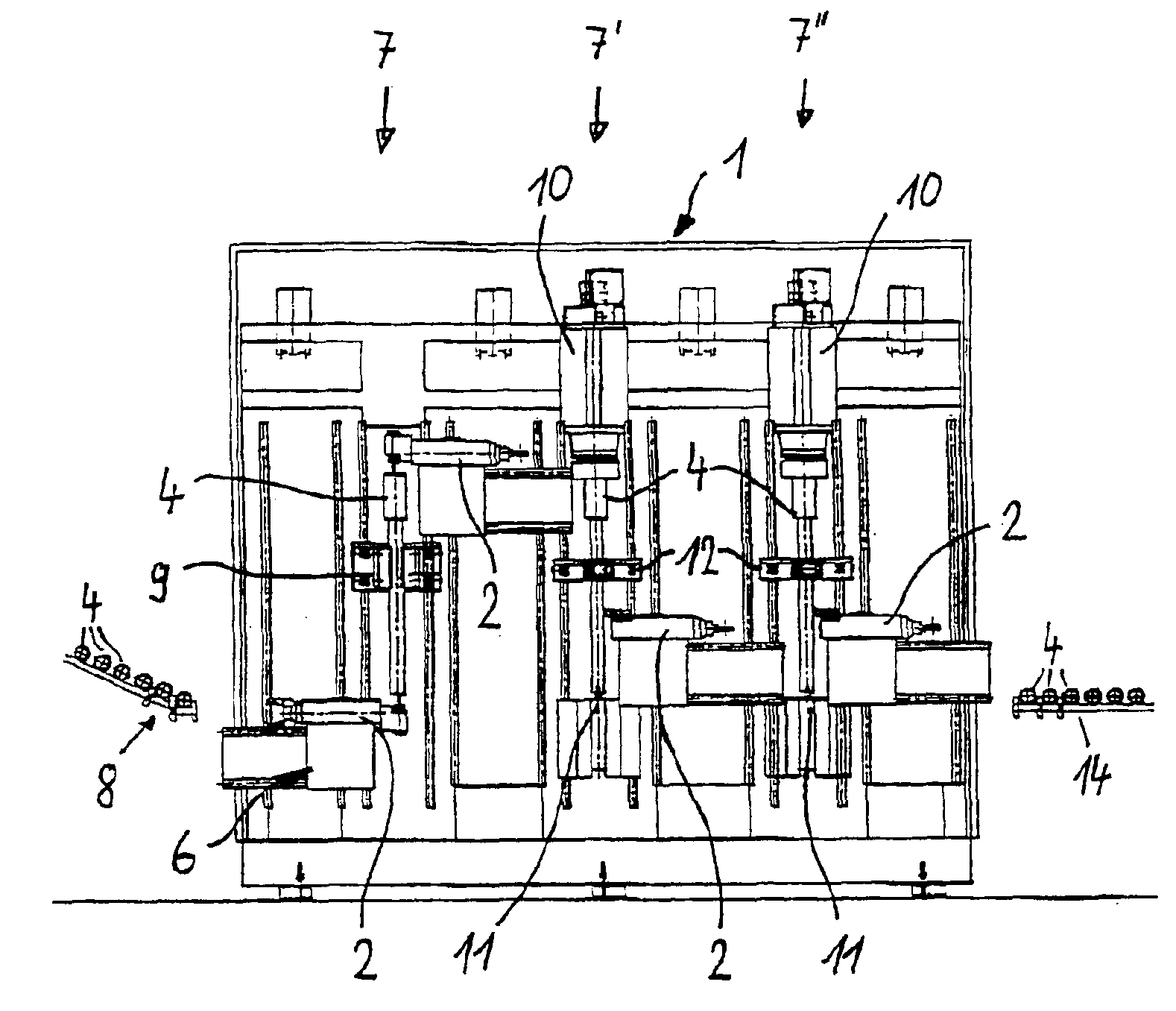
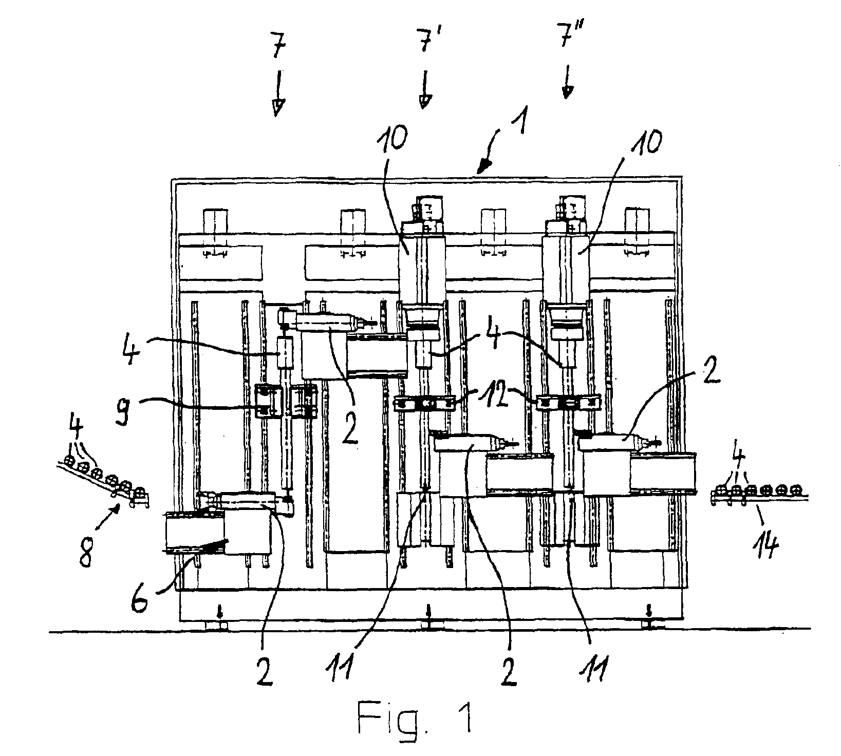
[0019]FIG. 1 shows a machine tool 1, in which components that are not essential for the invention, in particular details of the drive, the control, and the housing, are not illustrated in order to provide a better overview. The described machine tool is particularly suitable for machining workpieces 4 of wavy shape, and the following description pertains to wavy workpieces 4. The machine tool 1 consists of three successively arranged machining stations 7, 7′, 7″, wherein it is assumed that the workpiece 4 arriving from the workpiece feed station 8 in the form of a magazine is transported to the machining stations 7, 7′, 7″, and that processing of the workpiece 4 takes place in each machining station. The machining may differ from station to station, or be carried out similarly or identically in accordance with the so-called step-by-step method. In the embodiment shown, the workpiece 4 is machined differently in the successive machining stations 7, 7′, 7″.

[0020]In FIG. 1, the workpie...


PUM

PropertyMeasurementUnit
timeaaaaaaaaaa
rotationaaaaaaaaaa
flexibleaaaaaaaaaa

Abstract

Method and apparatus providing a tool turret for a machine tool with at least one motor-driven tool that is suitable for machining of wavy or tubular workpieces. The transport of the workpieces from one machining station to the next is effected in a simpler, more reliable, and less expensive fashion, because the machine tool has a tool turret that includes a gripping element for taking hold of, transporting, and positioning workpieces, rather than using an additional tool.

Description

BACKGROUND OF THE INVENTION[0001]1. Field of the Invention[0002]The invention relates to a method and apparatus for machining workpieces, and more particularly to a machine tool equipped in a novel way with a tool turret to enable machining of wavy or tubular workpieces.[0003]2. Prior Art[0004]EP 0 978 351 A2 describes a device for machining workpieces with at least two adjacently arranged lathes that respectively contain a vertically arranged, rotationally driven work spindle for clamping the workpiece and at least one device for accommodating several machining tools. The rotational axes of all lathes are essentially arranged vertically in this case, and one rotating / pivoting device is respectively provided between the lathes in order to transfer the workpiece from one lathe to the next lathe after each respective machining step is completed. One disadvantage of this arrangement can be seen in the fact that a completely separate lathe with its own control, its own drive, and its ow...

Claims


Application Information

Patent Timeline
Patent Type & Authority Patents(United States)
IPC IPC(8): B23Q39/00B23Q39/04B23Q7/04B23B3/22B23B9/06B23B13/04B23B15/00B23Q41/02
CPCB23Q7/045B23Q39/04B23Q39/048Y10T29/5136Y10T29/5124B23Q7/04
Inventor WALZ, JUERGEN
Owner EMAG HLDG GMBH
Why Eureka
Try Eureka