Chassis with energy-absorption zones

a technology of energy absorption and chassis, which is applied in the direction of wheelchairs/patients, electric devices, driver input parameters, etc., can solve the problems of inability to use “off-the-shelf” components and linkages for new or different bodies, and the componentry of one vehicle body configuration is typically not compatible with other vehicle body configurations, so as to increase the functionality of their vehicles, increase manufacturing efficiency, and reduce cost

Inactive Publication Date: 2005-06-14
GM GLOBAL TECH OPERATIONS LLC
View PDF63 Cites 31 Cited by
  • Summary
  • Abstract
  • Description
  • Claims
  • Application Information

AI Technical Summary

Benefits of technology

[0011]The invention also allows a multitude of body configurations to share a common chassis, enabling economies of scale for major mechanical, electrical, and structural components.
[0012]Connection components, exposed and unobstructed, increase manufacturing efficiency because attachment of a body to the chassis requires only engagement of the connection components to respective complementary connection components on a vehicle body.
[0013]Vehicle owners can increase the functionality of their vehicles at a lower cost than possible with the prior art because a vehicle owner need buy only one chassis upon which to mount a multitude of body styles.

Problems solved by technology

The nature of the prior art connections between a vehicle body and vehicular componentry may result in certain inefficiencies in the design, manufacture, and use of vehicles.
Mechanical linkages result in inefficiencies, in part, because different driver locations in different vehicles require different mechanical linkage dimensions and packaging.
Thus, new or different bodies often cannot use “off-the-shelf” components and linkages.
Componentry for one vehicle body configuration is typically not compatible for use with other vehicle body configurations.
The location of the connections on prior art vehicle bodies and componentry also results in inefficiencies.
The vehicle body of a fully-assembled prior art vehicle is intertwined with the componentry and the connection devices, rendering separation of the body from its componentry difficult and labor-intensive, if not impossible.
Furthermore, prior art vehicles typically have internal combustion engines that have a height that is a significant proportion of the overall vehicle height.
For example, a vehicle body with an engine compartment in the rear is not compatible with a chassis with an engine in the front.

Method used


Image

  • Chassis with energy-absorption zones
  • Chassis with energy-absorption zones
  • Chassis with energy-absorption zones

Examples


Embodiment Construction

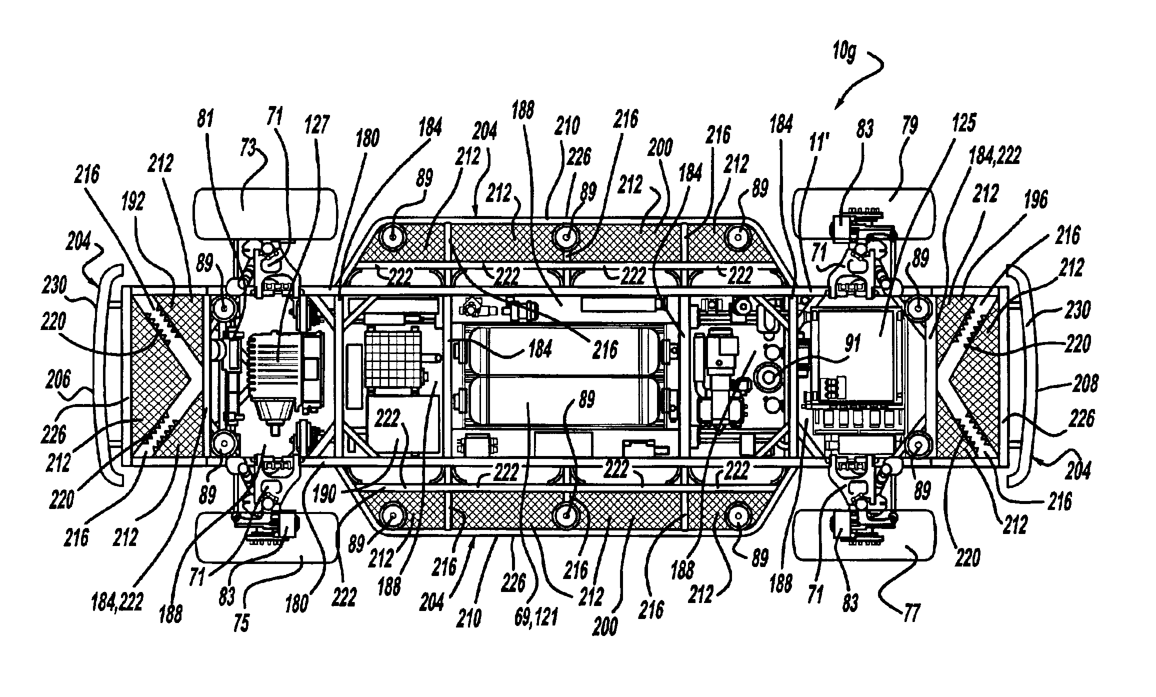
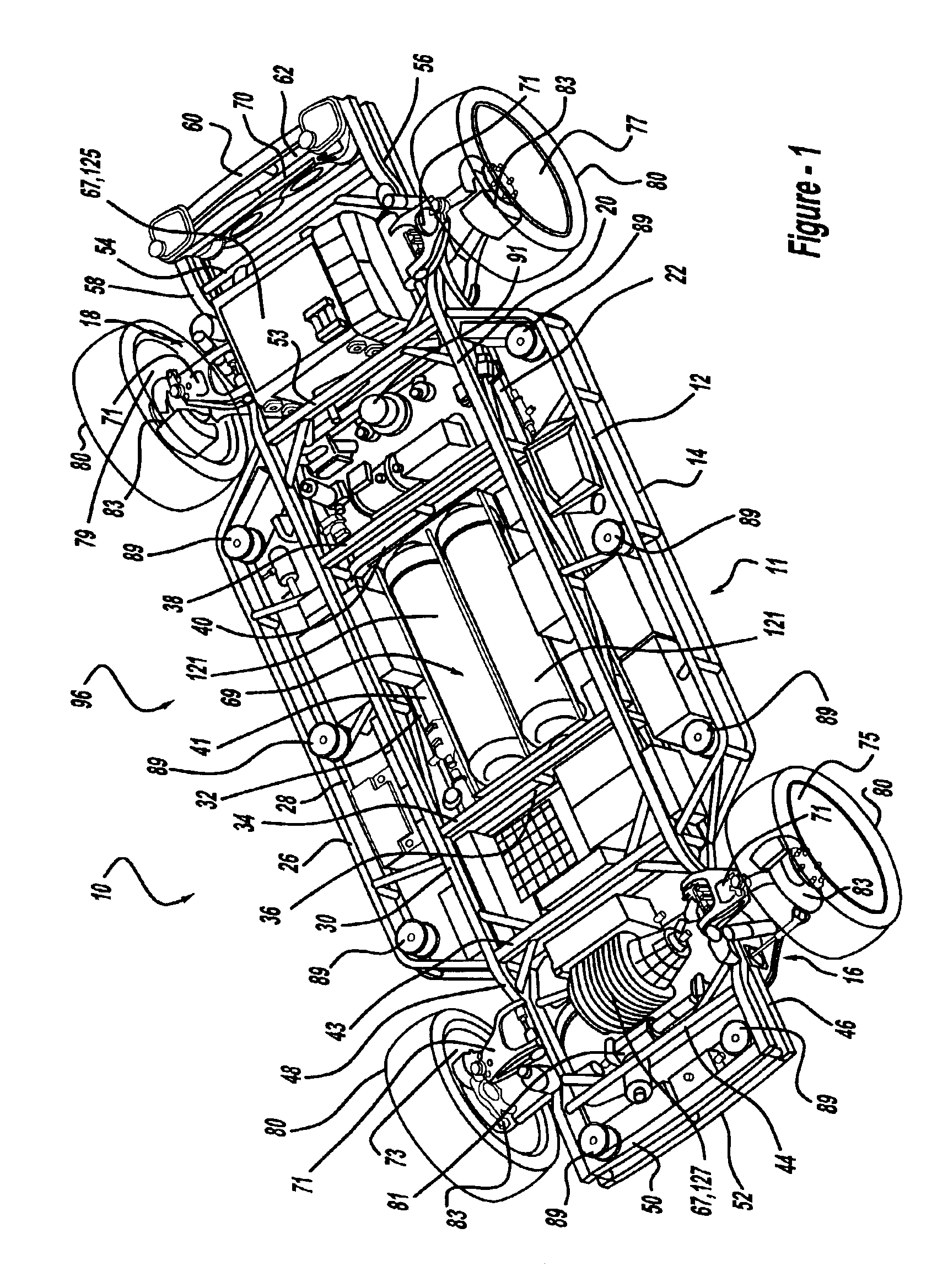
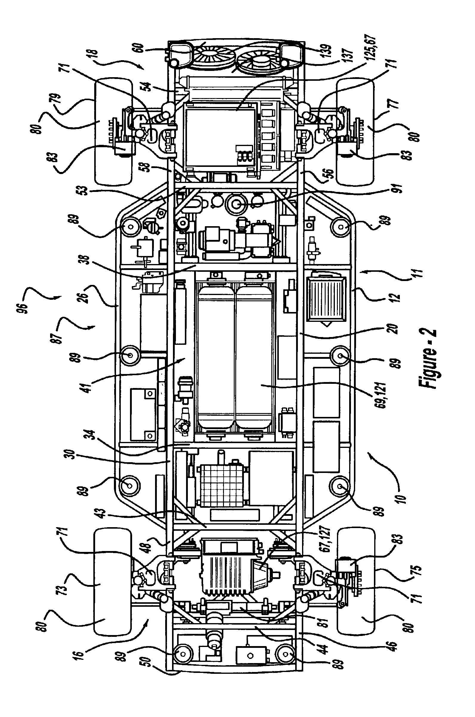
[0037]Referring to FIG. 1, a vehicle chassis 10 in accordance with the invention, also referred to as the “rolling platform,” includes a structural frame 11. The structural frame 11 depicted in FIG. 1 comprises a series of interconnected structural elements including upper and lower side structural elements 12 and 14 that comprise a “sandwich”-like construction. Elements 12 and 14 are substantially rigid tubular (or optionally solid), members that extend longitudinally between the front and rear axle areas 16, 18, and are positioned outboard relative to similar elements 20, 22. The front and rear ends of elements 12, 14 are angled inboard, extending toward elements 20 and 22 and connecting therewith prior to entering the axle areas 16, 18. For added strength and rigidity a number of vertical and angled structural elements extend between elements 12, 14, 20 and 22. Similar to the elements 12, 14, 20 and 22, which extend along the left side of the rolling platform 10, a family of stru...


PUM


Abstract

A chassis having systems responsive to nonmechanical control signals and a simplified body-attachment interface includes regions optimized for energy absorption from an impact to the chassis periphery. A structural frame defines open spaces within which chassis systems are positioned. Material configured to absorb energy from an impact to the chassis periphery is located between the chassis periphery and the open spaces.

Description

CROSS-REFERENCE TO RELATED APPLICATIONS[0001]This application claims the benefit of U.S. Provisional Application 60 / 337,994, filed Dec. 7, 2001, which is hereby incorporated by reference in its entirety.TECHNICAL FIELD[0002]This invention relates to vehicle chassis with systems responsive to nonmechanical control signals, a simplified body-attachment interface, and regions configured for energy absorption.BACKGROUND OF THE INVENTION[0003]Mobility, being capable of moving from place to place or of moving quickly from one state to another, has been one of the ultimate goals of humanity throughout recorded history. The automobile has likely done more in helping individuals achieve that goal than any other development. Since its inception, societies around the globe have experienced rates of change in their manner of living that are directly related to the percentage of motor vehicle owners among the population.[0004]Prior art automobiles and light trucks include a body, the function of...

Claims


Application Information

Patent Timeline
Patent Type & Authority Patents(United States)
IPC IPC(8): B60G17/015B60G3/18B60H1/00B60G7/00B60K1/00B62D24/00B62D24/02B62D65/00B60T1/06B62D29/00B62D35/02B60N2/44B60K15/03B62D5/00B60K15/07B62D35/00B62D21/10B62D65/04B60T13/66B60T1/10B60T13/74B60T1/00B60T13/00B62D21/15B60T7/00B60T7/04B60T8/00B62D21/00G06Q30/00B60G13/14B60G17/0195B60K1/04B60K7/00B60K11/04B60K11/08B60K26/02B60N2/14B60N2/90B62B3/12B62D1/02B62D1/22B62D21/02G01M1/38
CPCB60G3/18B60G7/003B60G13/14B60G17/015B60G17/0195B60H1/004B60K1/00B60K1/04B60K15/07B60K41/202B60K41/28B60N2/14B60N2/44B60T1/065B60T1/10B60T7/00B60T7/042B60T8/00B60T13/66B60T13/662B60T13/74B62B3/12B62D1/02B62D1/22B62D5/00B62D21/00B62D21/10B62D21/15B62D24/02B62D29/008B62D35/02B62D63/025B62D65/04G06Q30/06B60L7/16B60L15/2009B60G2200/10B60G2200/144B60G2200/18B60G2200/44B60G2200/46B60G2200/462B60G2202/40B60G2202/42B60G2204/10B60G2204/11B60G2204/14B60G2204/16B60G2204/20B60G2204/202B60G2206/011B60G2206/0114B60G2206/50B60G2206/99B60G2300/45B60G2300/50B60G2300/60B60G2800/21B60G2800/802B60G2800/90B60G2800/91B60G2800/92B60G2800/963B60K7/0007B60K2001/001B60K2001/005B60K2741/205B60K2741/28B60T2270/82B60Y2200/84B60L2220/44B60L2240/12B60L2240/423B60L2250/16B60L2250/26B60L2260/28Y02T90/16Y02T10/7275Y02T10/642B60L2200/46B60L2270/40B60W10/18B60W10/20B60W10/24B60W30/18B60W2520/10B60W2520/105B60W2520/125B60W2520/14B60W2520/28B60W2540/18B60N2/90Y02T10/64Y02T10/72Y02T10/88
Inventor BORRONI-BIRD, CHRISTOPHER E.CHERNOFF, ADRIAN B.SHABANA, MOHSEN D.VITALE, ROBERT L.
Owner GM GLOBAL TECH OPERATIONS LLC
Why Eureka
Try Eureka