Bidirectional side dump trailer with improved tub lift system

a dump trailer and lift system technology, applied in the field of dump trailers with containment tubs, can solve the problems of tub corner cracking, rogers' design does not allow the use of containment tubs, and suffer from a number of deficiencies

Inactive Publication Date: 2005-06-14
SMITHCO MFG
View PDF6 Cites 24 Cited by
  • Summary
  • Abstract
  • Description
  • Claims
  • Application Information

AI Technical Summary

Benefits of technology

[0010]In view of the foregoing structure, it is an object of the present invention to provide a bidirectional side dump trailer with a lifting mechanism that distributes the lift force over a greater area to allow the associated stresses applied on the container tub to be minimized. Such distribution of the lift force presents the option to use lighter weight material (such as aluminum) in the containment tub ultimately providing greater payloads. It is a further advantage of the present invention to provide a lifting mechanism that requires a relatively low volume of hydraulic fluid for controlling the lift system. It is an additional object of the invention to provide a mechanism that not only allows for the possibility of a greater dump angle for the container tub, but also serves to locate the hydraulic cylinders of the lift mechanism in a location where they are protected beneath the containment tub.
[0011]The present invention provides a bidirectional side dump trailer for hauling material that is suitable for dumping from either side of the trailer. The invention includes a wheeled frame, a containment tub mounted upon tub supports secured to the frame, locking means located on the tub and the trailer for releasable securement of the tub to the trailer and tub lifting means comprised of at least two power cylinders located at a generally medial location underneath the containment tub.
[0012]In a preferred embodiment, the power cylinders each have lower ends pivotally secured to a generally medial portion of said trailer and upper ends pivotally secured to the bottom of said containment tub so that the cylinders define a front power cylinder and a rear power cylinder generally in alignment with one another. The wheeled frame includes a plurality of transverse support struts extending between the opposite sides thereof, and the bottom ends of the power cylinders are secured to at least one of the support struts of said frame.
[0013]The foregoing and other advantages of the present invention will appear from the following description. In the description, reference is made to the accompanying drawings, which form a part hereof, and in which there is shown by illustration and not of limitation a specific form in which the invention may be embodied. Such embodiment does not represent the full scope of the invention, but rather the invention may be employed in a variety of other embodiments and reference is made to the claims herein for interpreting the breadth of the invention.

Problems solved by technology

Although the Rogers' type of lifting system for the trailer tub has proved useful, it suffers from a number of deficiencies.
Secondly, the application of pressure on the ends of the containment tub often results in tub corner cracking as a result of the localization of lifting pressure thereon.
Thirdly, the Rogers' design does not allow for the use of containment tubs that are longer than the trailer frame and, in many instances, it is beneficial to be able to use longer tubs when the hauling of maximum loads is required.
Although the embodiments disclosed by Golden seem to eliminate the deficiencies of having end located power cylinders, as pointed out in the '211 patent, in column 10 due to the use of a single connection point between the lift system and the container tub, the stress on the base wall of the containment tub is extreme and requires further structural strength for the tub.

Method used


Image

  • Bidirectional side dump trailer with improved tub lift system
  • Bidirectional side dump trailer with improved tub lift system
  • Bidirectional side dump trailer with improved tub lift system

Examples


Embodiment Construction

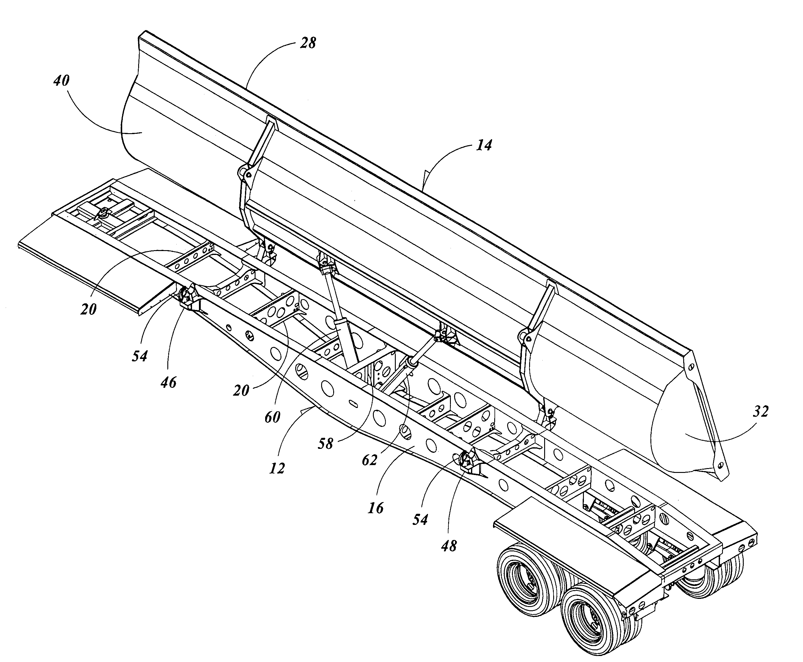
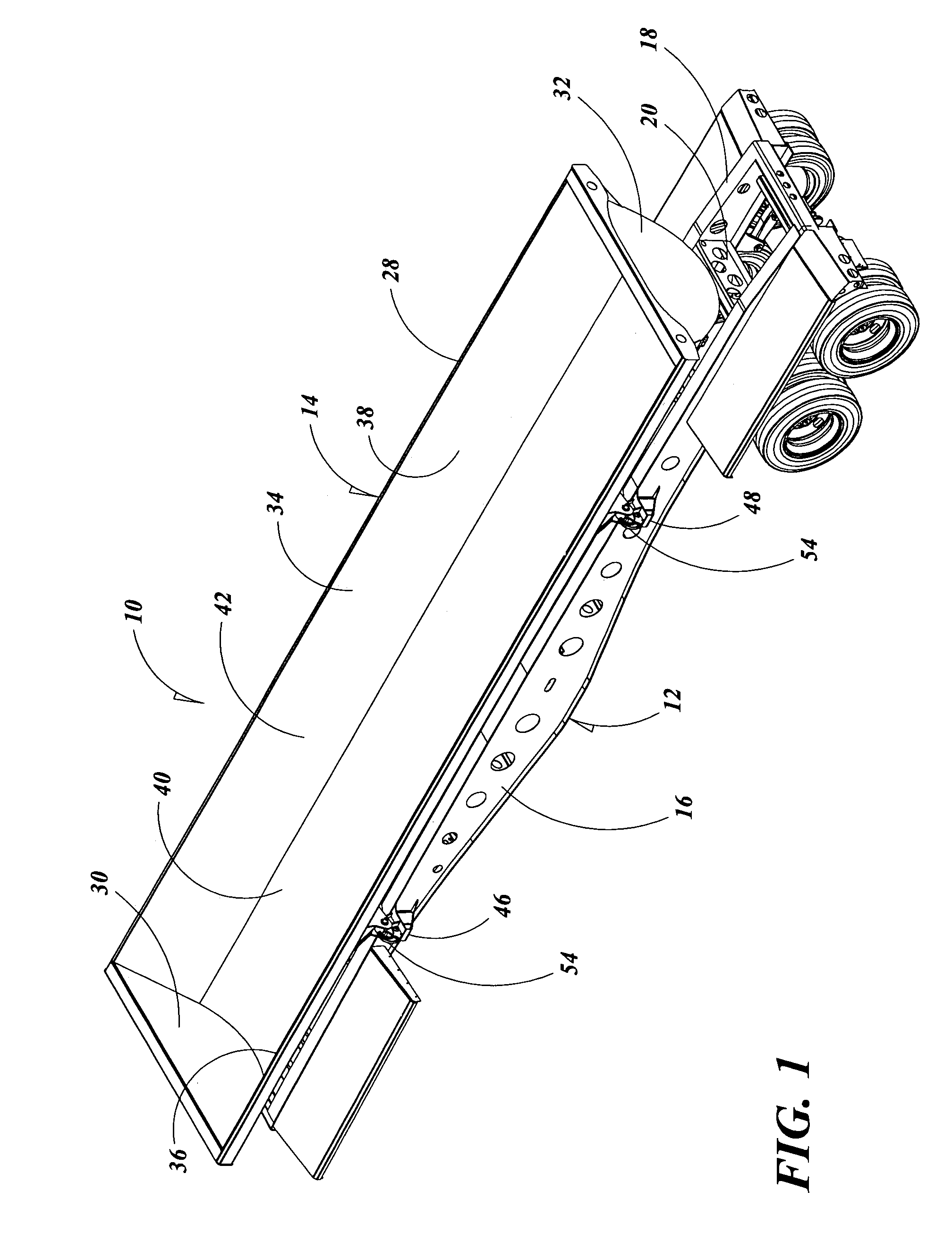
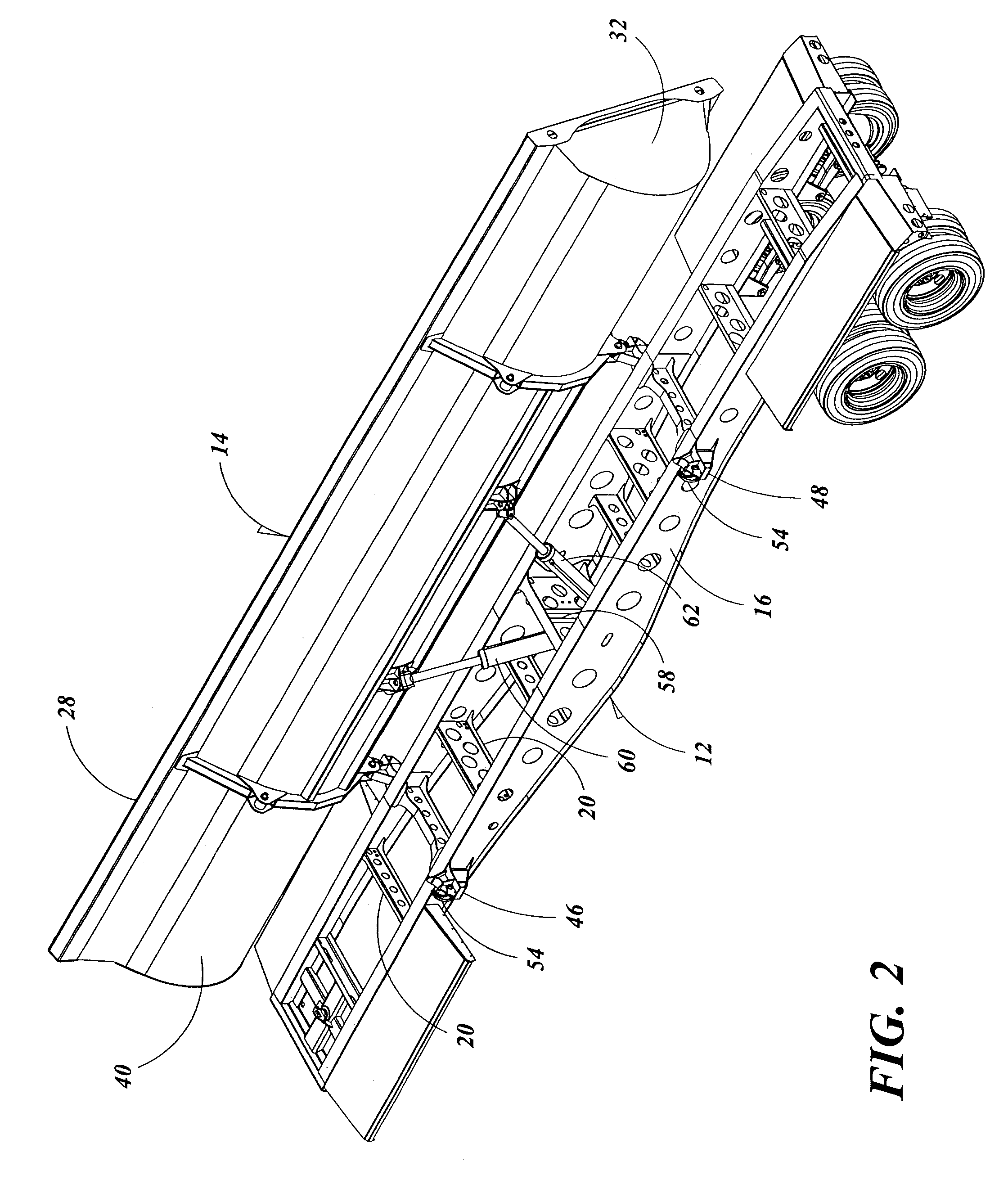
[0020]Referring now to the drawings and with reference first to FIG. 1, a preferred embodiment of the bidirectional side dump trailer of the present invention is shown at 10 that is particularly adapted for hauling rock, dirt, gravel and other types of solid material. The trailer 10 includes a wheeled frame 12 on which is pivotally mounted a containment tub 14. The wheeled frame 12 is formed from two spaced apart main sidewalls 16 and 18 that are secured together by a plurality of transverse support struts 20. Although the frame 12 is depicted as being adapted for being pulled by a truck, it should be understood that the frame 12 could also be part of the truck if desired or towed by farm tractor via a hitch.

[0021]The containment tub 14 has an elongated body 28 including a front wall 30, a rear wall 32 and an arcuate shaped trough 34 formed with side portions 36 and 38 and a bottom portion 40. The trailer body 28 has an open top 42 through which materials to be hauled can be loaded ...


PUM


Abstract

A directional side dump trailer having a wheeled frame for supporting a containment tub for receiving material to be dumped, which tub is releasably attached to the frame by locks, and at least a pair of power cylinders secured to the tub and the trailer and located generally below the containment tub.

Description

BACKGROUND OF THE INVENTION[0001]1. Field of the Invention[0002]The present invention relates in general to dump trailers having a containment tub that can be emptied from either of its sides rather than from its rear end and more specifically relates to a lift system for the tub that is designed to better distribute pressure being exerted on the tub ends during the dumping process.[0003]2. Description of the Prior Art[0004]Bidirectional side dump trailers that include a pivotally mounted containment tub to permit dumping of a load from either side of a trailer rather than the trailer rear end have been known in the prior art for many years and have achieved acceptance in the marketplace since the early 1990's. Such trailers are particularly useful in situations such as during road construction when it is often necessary to dump numerous large loads of rock or gravel along the sides of roadbeds or for conducting ground leveling activity.[0005]A variety of different types of bidirect...

Claims


Application Information

Patent Timeline
Patent Type & Authority Patents(United States)
IPC IPC(8): B60P1/16B60P1/04
CPCB60P1/165
Inventor VERROS, JAMES M.
Owner SMITHCO MFG
Why Eureka
Try Eureka