Process for creating expandable tire chamber

Inactive Publication Date: 2005-06-14
Q TIRES
View PDF13 Cites 40 Cited by
  • Summary
  • Abstract
  • Description
  • Claims
  • Application Information

AI Technical Summary

Problems solved by technology

Even then blow outs were common occurrences and such were considered a major hazard of driving.
Today a blow out is almost unheard of and a set

Method used


Image

  • Process for creating expandable tire chamber
  • Process for creating expandable tire chamber
  • Process for creating expandable tire chamber

Examples


Embodiment Construction

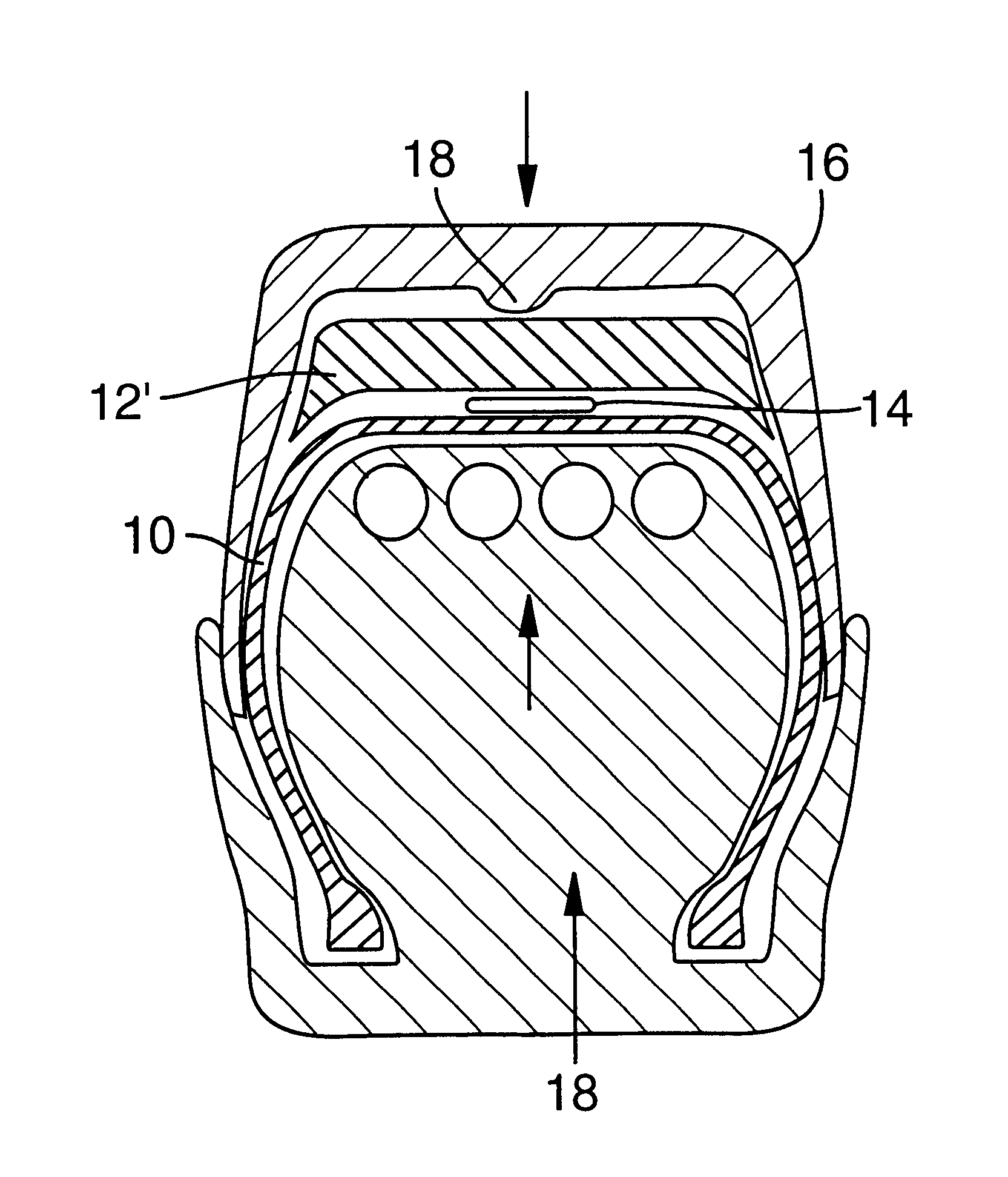
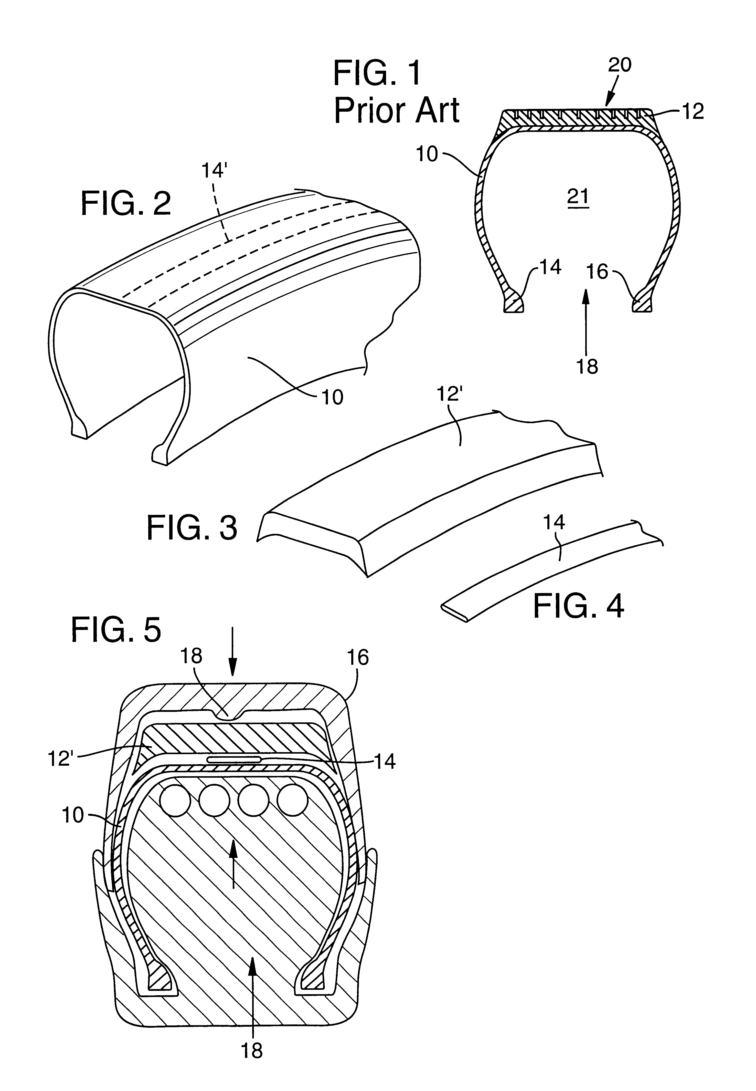
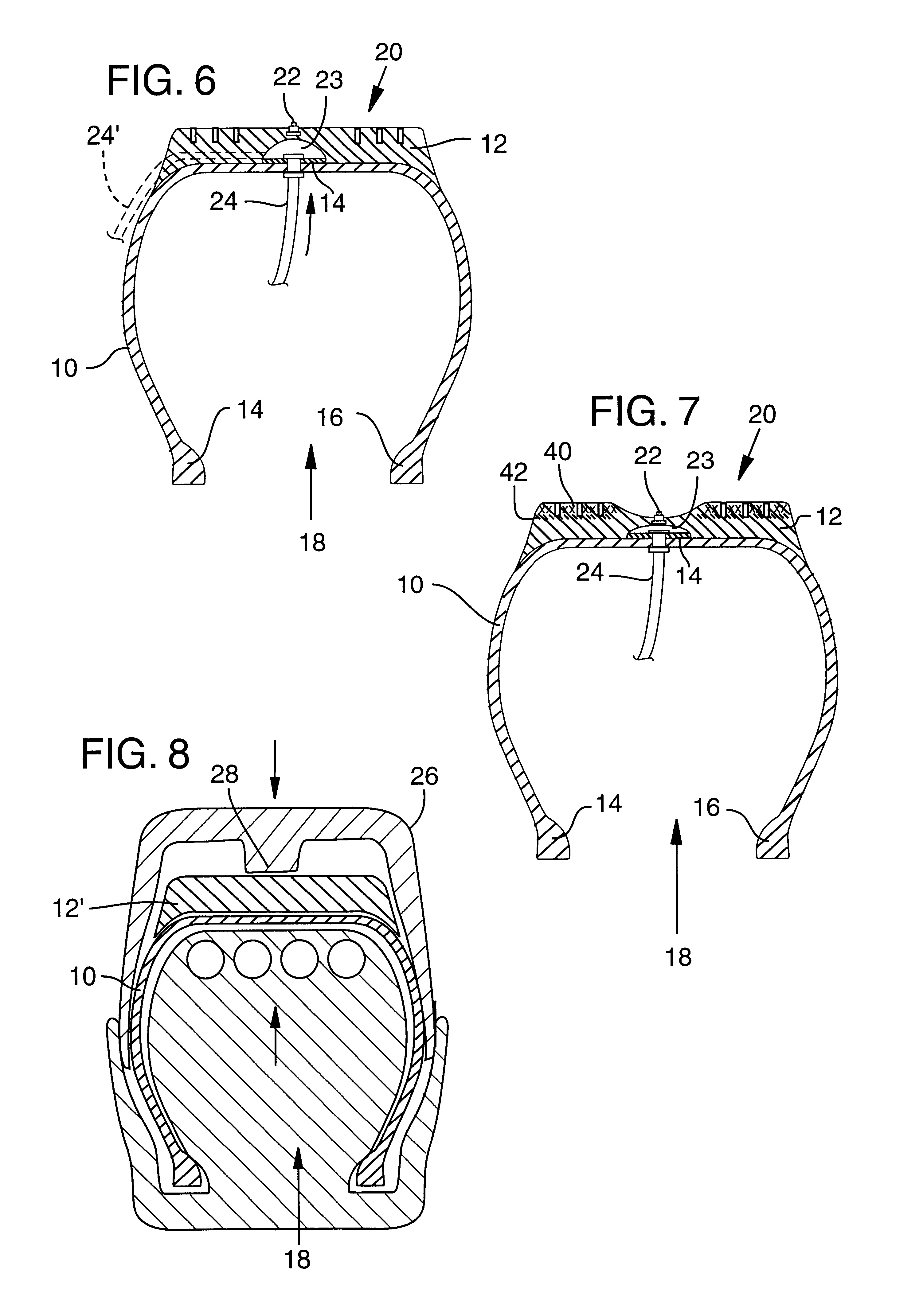
[0008]The invention provides for the formation of a secondary air chamber (the first chamber occupying the space 21 inside the casing 10). This secondary chamber is preferably formed at the interface between the casing and the tread. Studs may be imbedded in the portion of the tread that overlies the secondary air chamber and the tread thickness of that portion is reduced and inset into the tire tread so that the studs do not extend to the tread periphery. They are preferably inset to an extent that they do not extend to the tread periphery until 60 percent of the usable tread thickness is worn away.

[0009]The formation of the reduced thickness of the tread is formed by configuring the mold form to form an indentation in the tread face during the molding process. The secondary air chamber is formed by placing a non-adhering material such as tape, powder, liquid, e.g., in the form of a Teflon™ tape on the casing surface and surrounding the casing. When the tread rubber is bonded to th...


PUM


Abstract

A process for producing a tire having an expandable chamber utilized for extending and retracting studs provided in the periphery of the tire. In one embodiment, a non-stick film is strategically positioned between the casing and the tread prior to curing the tread onto the casing. The interface at either side of the film forms the sides of an expandable chamber. The tread side of the chamber is inset and studs are affixed thereto. Expansion of the chamber extends the studs out of the inset and into engagement with a road surface. Alternative processes provide a channel in the tread and the expansion chamber formed in the channel.

Description

[0001]This is a continuation-in-part of U.S. application Ser. No. 09 / 284,557 filed on Apr. 14, 1999, which was the National Stage of International Application No. PCT / US97 / 19454, filed Oct. 17, 1997, now U.S. Pat. No. 6,386,252; which is a continuation-in-part of U.S. application Ser. No. 08 / 909,302 filed on Aug. 11, 1997, now U.S. Pat. No. 5,810,451; which is a continuation-in-part of U.S. application Ser. No. 08 / 733,676 filed on Oct. 17, 1996, now U.S. Pat. No. 5,788,335.FIELD OF THE INVENTION[0002]This invention relates to a process for creating a secondary expandable chamber cooperatively arranged with an extendable portion of the tire tread to provide the means to induce independent engagement and disengagement of that portion with a road surface.BACKGROUND OF THE INVENTION[0003]This invention is a further development to the commonly owned inventions of U.S. Pat. Nos. 5,788,335 and 5,810,451, the disclosures of which are incorporated herein by reference.[0004]Whereas the concep...

Claims


Application Information

Patent Timeline
IPC IPC(8): B60B15/26B60B15/00H04N9/04H04N3/15B29D30/66
CPCB29D30/66B60B15/266B60B15/10B29D2030/662
Inventor O'BRIEN, JOHN M.LEWIS, DANNY ROBERTBUSHNELL, RAYMOND BRYCEOLSON, CHARLES DAMON
Owner Q TIRES
Why Eureka
Try Eureka