Intelligent appliance home network

a smart appliance and home network technology, applied in the field of consumer devices, can solve the problems of cost-prohibitive for most users, additional cost associated with providing, and the cost of replacing every legacy appliance in one's home to obtain such intelligent appliances, and achieve the effects of enhancing the physical security of the appliance, consuming high power substantially continuously, and being easy to implemen

Inactive Publication Date: 2005-06-14
VIDEO STREAMING SOLUTIONS
View PDF13 Cites 315 Cited by
  • Summary
  • Abstract
  • Description
  • Claims
  • Application Information

AI Technical Summary

Benefits of technology

[0008]It is an object of this inventing to provide a method for communicating a status of an appliance that is easy to implement regardless of the capabilities of the appliance. It is a further object of this invention to provide a method for communicating a status of an appliance without requiring a modification to the appliance. It is a further object of this invention to provide an appliance-independent device that can provide status information that can be used to determine the status of its associated appliance. It is a further object of this invention to provide a method and device to enhance the physical security of the appliances in a home-automation system.

Problems solved by technology

Such a bidirectional information flow capability, however, is typically available only from fairly sophisticated appliances, such as home-entertainment systems, wherein the additional cost associated with providing the “intelligence” required is insubstantial, or deemed to be worthwhile to effect a product differentiation.
Also, even if a majority of future appliances contain sufficient intelligence to communicate their status to a home automation system, the cost of replacing every legacy appliance in one's home to obtain such intelligent appliances will be cost-prohibitive to most users.

Method used


Image

  • Intelligent appliance home network
  • Intelligent appliance home network
  • Intelligent appliance home network

Examples


Embodiment Construction

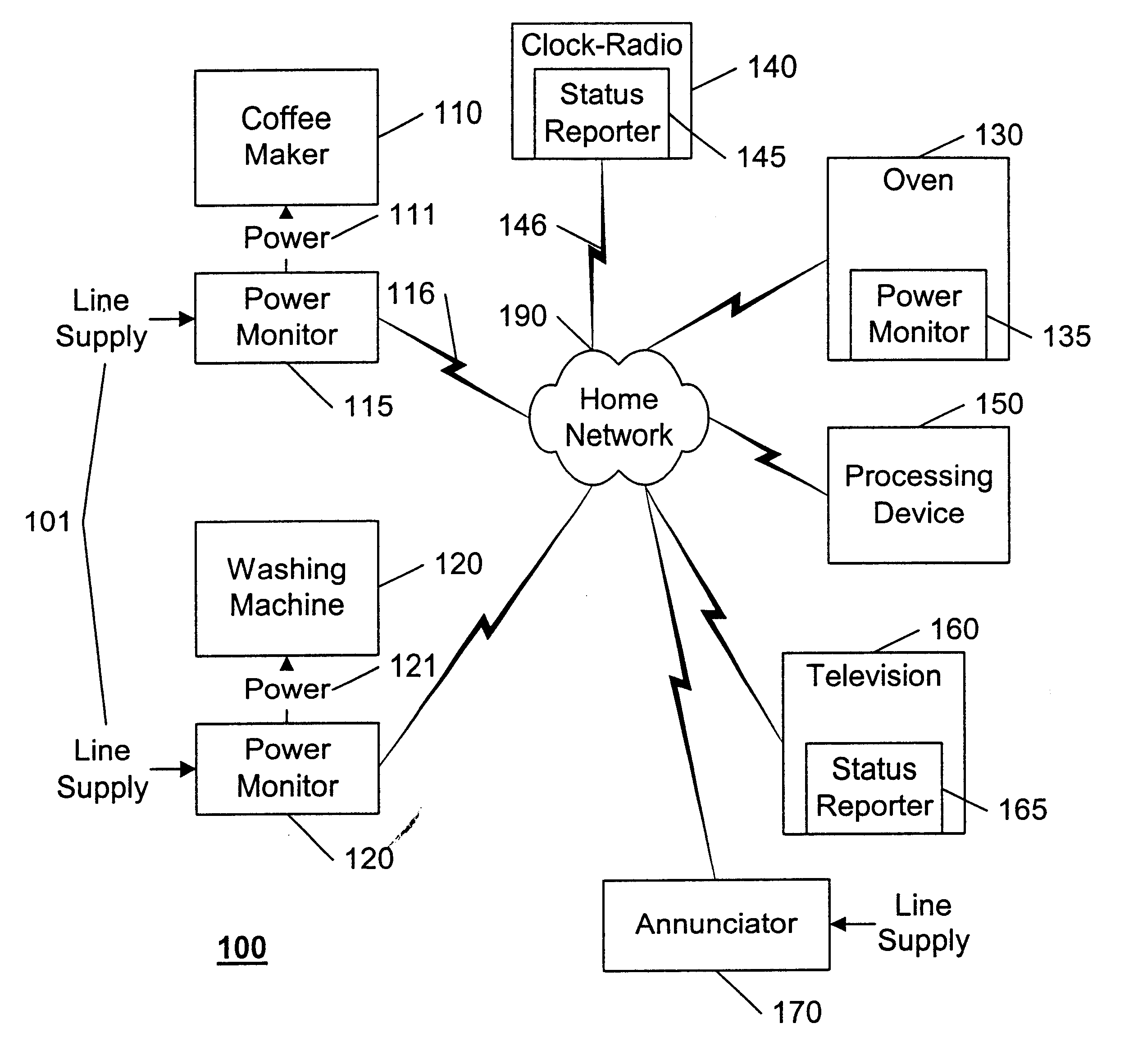
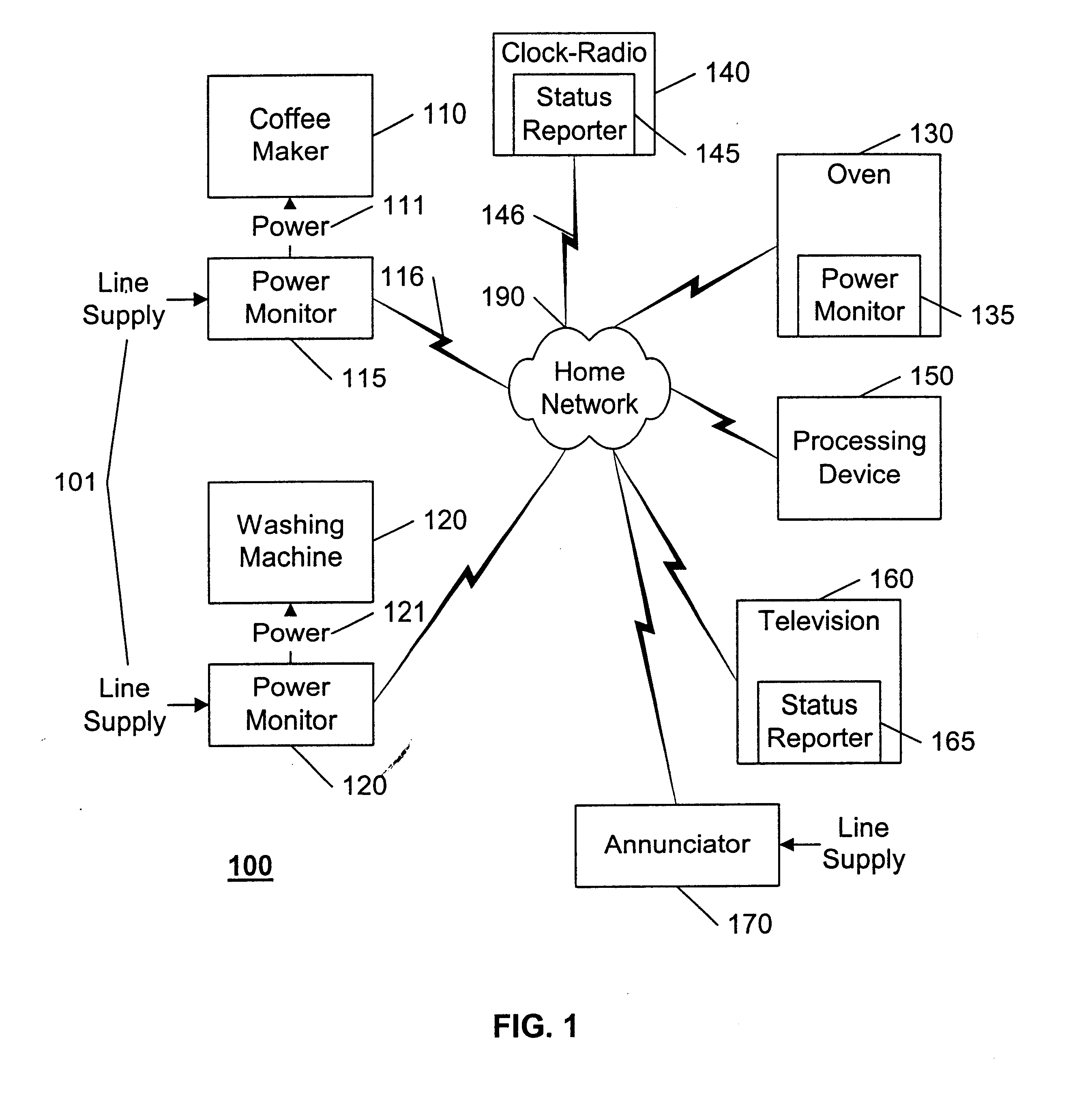
[0019]FIG. 1 illustrates an example block diagram of a home-automation system 100 in accordance with this invention. The home-automation system 100 includes a variety of appliances 110, 120, 130, 140, and 160 and ancillary devices 115, 125, 135, 145, 150, and 170 that facilitate the communication and processing of information and commands related to the appliances 110, 120, 130, 140, and 160 or other systems within a home. For ease of understanding, an appliance is defined herein as a device that has a primary function, such as making coffee, washing clothes, providing entertainment, and the like, that is substantially independent of providing automation information and control.

[0020]In accordance with this invention, at least one appliance 110 includes a power monitor device 115 that provides a measure 116 of the power 111 consumed by the appliance 110 to a processing device 150. Based on a sequence of these measures 116, the processing device 150 determines a state of the applianc...


PUM


Abstract

The instantaneous power consumption of an appliance is used to determine the status of the appliance, from which further actions may be taken. This invention is premised on the observation that most appliances have a characteristic power consumption pattern that can be used to determine the state of operation of the appliance. An electric coffee pot, for example, consumes high power substantially continuously during the brewing state, then reduces its power level, or power duration, or both, while keeping the pot warm, then terminates its power consumption when it is turned off. In like manner, the power consumption patterns of other appliances, such as toasters, washing machines, dryers, and so on may also be used to determine the state of each appliance. The communicated state may be used by a home-automation system to effect a variety of actions, including notifying the user, terminating the available power to the appliance, initiating an action by another appliance, and so on.

Description

BACKGROUND OF THE INVENTION[0001]1. Field of the Invention[0002]This invention relates to the field of consumer devices, and in particular to the field of automated home control systems.[0003]2. Description of Related Art[0004]Home automation is becoming increasingly popular. Standards continue to be developed which will allow devices of varying types and varying vendors to be controlled by a common controller. Such standards include IEEE 1394, X-10, HAVi, HomeAPI, Jini, and the like. IEEE 1394 and X-10 are communication protocols; HAVi is a software architecture using IEEE 1394; Home API is an open industry specification that defines a standard set of software services and application programming interfaces which enable software applications to monitor and control home device. Jini is a distributed software architecture (network) wherein clients see devices and services as objects.[0005]Some home automation systems may include a monitoring and reporting system that maintains a reco...

Claims


Application Information

Patent Timeline
Patent Type & Authority Patents(United States)
IPC IPC(8): G01R19/25H02J13/00H04L12/28H04L12/12G01R21/00G01R21/133G06Q10/00G06F13/00H04Q9/00
CPCG01R19/2513H02J13/001H02J13/002H04L12/12H04L12/2823H04L12/2803G01R21/133H02J2003/143Y04S40/121Y02B60/34Y02B70/325Y04S20/228Y02B90/2615H02J13/00001H02J13/00004H02J13/00007H02J2310/14Y02B70/30Y02B70/3225Y02B90/20Y04S20/20Y04S20/222Y04S20/242Y02D30/50H04L12/16
Inventor VAN DER MEULEN, PIETER SIERD
Owner VIDEO STREAMING SOLUTIONS
Why Eureka
Try Eureka