Magnetic disk apparatus and its servo signal recording method

a technology of magnetic disk and servo signal, which is applied in the direction of recording information storage, maintaining head carrier alignment, instruments, etc., can solve the problems of inability to verify whether required servo tracks have been written, and inability to record a servo signal. the throughput of an operation is considerably reduced

Inactive Publication Date: 2005-06-14
HITACHI GLOBAL STORAGE TECH JAPAN LTD
View PDF2 Cites 20 Cited by
  • Summary
  • Abstract
  • Description
  • Claims
  • Application Information

AI Technical Summary

Problems solved by technology

These hard variations exhibited by the recording / reproducing device of the head cause gap variations in actual servo tracks of the magnetic disk apparatus.
Thus, the conventional magnetic disk apparatus has a problem that it is impossible to verify whether required servo tracks have been written, that is, whether a servo signal has been recorded successfully, before verification of the number of servo tracks after the operation to record the servo signal onto the entire surface of the magnetic disk.
As a result, there is raised a problem that the throughput for an operation to record a servo signal decreases considerably.

Method used


Image

  • Magnetic disk apparatus and its servo signal recording method
  • Magnetic disk apparatus and its servo signal recording method
  • Magnetic disk apparatus and its servo signal recording method

Examples


Embodiment Construction

[0013]Preferred embodiments of the present invention are explained by referring to the diagrams as follows. It should be noted that a second embodiment's components identical with those employed in a first embodiment are no longer shown in diagrams and explanations of such identical components are not given in the description of the second embodiment to avoid duplication. Components common to both the embodiments and equivalent components shared by both the embodiments are denoted by the same reference numerals used in the first embodiment.

[0014]First of all, the first embodiment of the present invention is explained by referring to FIGS. 1 to 4.

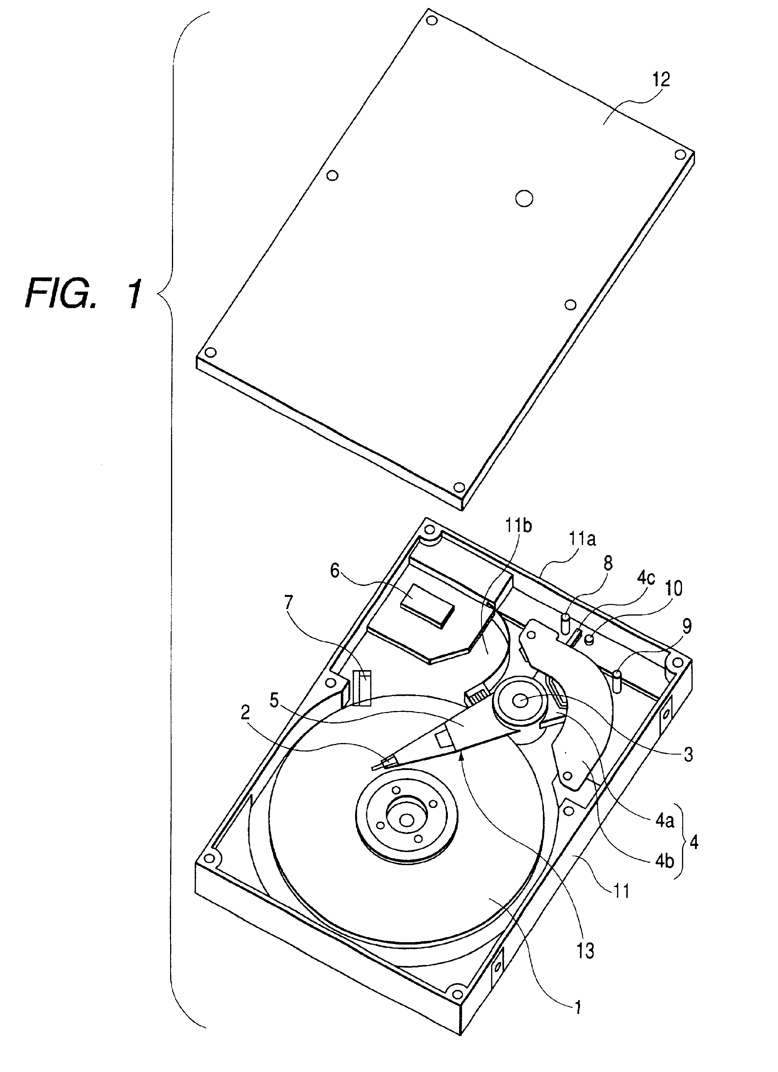
[0015]An overall configuration of this embodiment is explained by referring to FIG. 1.

[0016]A circular medium serving as a magnetic disk 1 for recording information is mounted on a spindle motor provided at the center of a case 11, and rotated at a high speed. The case 11 is a thin rectangular cabinet having a side wall 11a and a bottom wall...


PUM

PropertyMeasurementUnit
areaaaaaaaaaaa
hardaaaaaaaaaa
sizeaaaaaaaaaa

Abstract

A magnetic disk apparatus includes an actuator for moving a head to a position above the magnetic disk in a servo track movement operation, a range limiter for limiting a movable range of the actuator, a range specifier for setting a specific range of the actuator in the movable range of the actuator, and a control unit. The control unit enables writing a servo signal into the specific range at servo track movement pitch based on servo tracks recorded with the servo signal, correcting the servo track movement pitch on the basis of the number of servo tracks in the specific range and executing control to write the servo signal at corrected servo track movement pitch.

Description

FIELD OF THE INVENTION[0001]The present invention relates to a magnetic disk apparatus and its servo signal recording method. More particularly, the present invention relates to a magnetic disk apparatus having a self servo write function for recording a servo signal for positioning a head at a predetermined location on a magnetic disk without using an external write apparatus and relates to a servo signal recording method adopted by the magnetic disk apparatus.BACKGROUND OF THE INVENTION[0002]A self servo write method is disclosed in International Publication No. WO96 / 28814 (corresponding to Japanese Patent Laid-Open No. Hei10-504128) as a method adopted in a conventional magnetic disk apparatus. This method adopts a technique of setting a gap between servo tracks on which data is recorded. In accordance with this self servo write method, the magnetic disk apparatus itself records a pattern by using a head provided therein and sets a pitch of the head movement by using the amplitud...

Claims


Application Information

Patent Timeline
Patent Type & Authority Patents(United States)
IPC IPC(8): G11B5/596G11B21/02G11B21/10
CPCG11B5/59633G11B21/10
Inventor YASUNA, KEIYAMAGUCHI, TAKASHISUGIYAMA, KENICHIRO
Owner HITACHI GLOBAL STORAGE TECH JAPAN LTD
Why Eureka
Try Eureka