
Electronic ignition module with rev limiting

a technology of electronic ignition module and rev limit, which is applied in the direction of automatic ignition control, machines/engines, instruments, etc., can solve the problems of excessive engine rpm, engine may be turned too quickly, and endanger bystanders

Inactive Publication Date: 2013-11-19
MARTINSON LAURA J +2
View PDF60 Cites 3 Cited by
  • Summary
  • Abstract
  • Description
  • Claims
  • Application Information

AI Technical Summary

Benefits of technology

The patent is about a replacement for car ignition modules that can be easily installed and adjusted while the car is running. The replacement can change the way the car engine reacts to the driver's actions, making it smoother and more efficient. The invention also includes multiple set points for the desired engine speed, as well as programmed timing curves and the ability to change programming through an input connector. This replacement can help drivers achieve better performance and comfort while driving.

Problems solved by technology

Unfortunately, and for a variety of reasons, an engine may be turned too quickly.
For exemplary purposes only, and not limiting the present disclosure thereto, slip during acceleration, a slipping or blown clutch, a missed gear, failure to engage the clutch before fully opening the throttle, component failure such as a transmission failure, carelessness, and other such factors can lead to excessive engine RPMs.
This can lead to engine failure, and may even result in an explosion or flying debris that can endanger bystanders.
The aforementioned and other events that can lead to excessive RPMs can be further compounded by already high RPMs such as frequently occur during a race or upon traversing inconsistent or unpredictable surfaces such as ice or snow-packed roadways.
Such stock ignition systems also do not usually provide over-rev protection.
As a result, the operation and performance of the engine is compromised.

Method used


Image

  • Electronic ignition module with rev limiting
  • Electronic ignition module with rev limiting
  • Electronic ignition module with rev limiting

Examples


Embodiment Construction

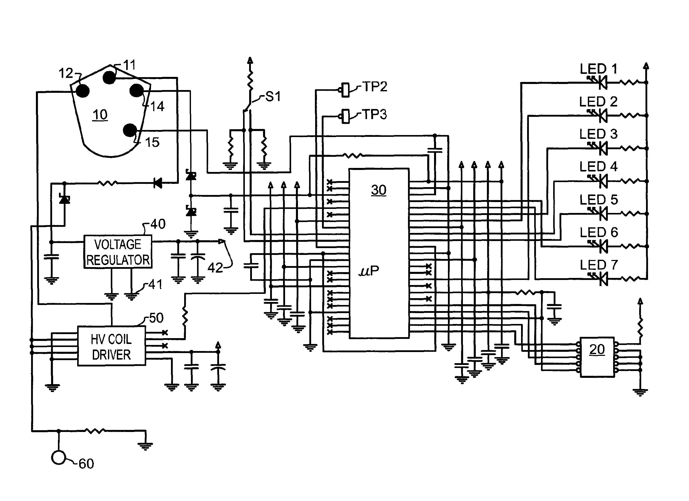
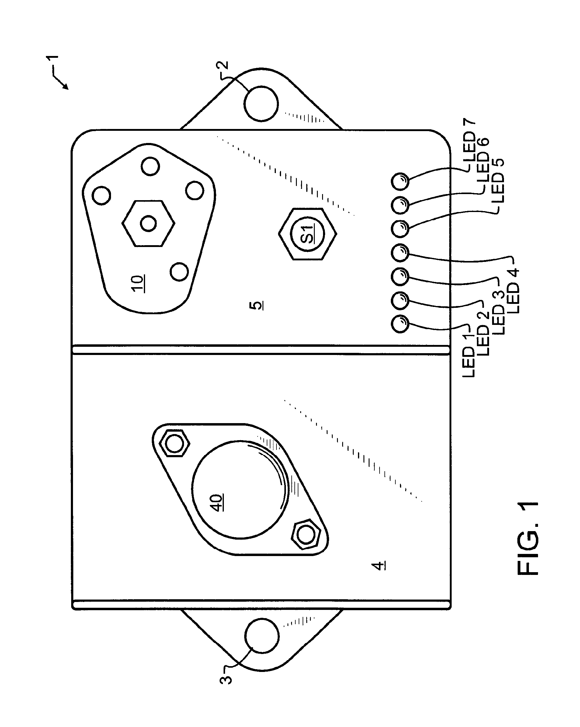
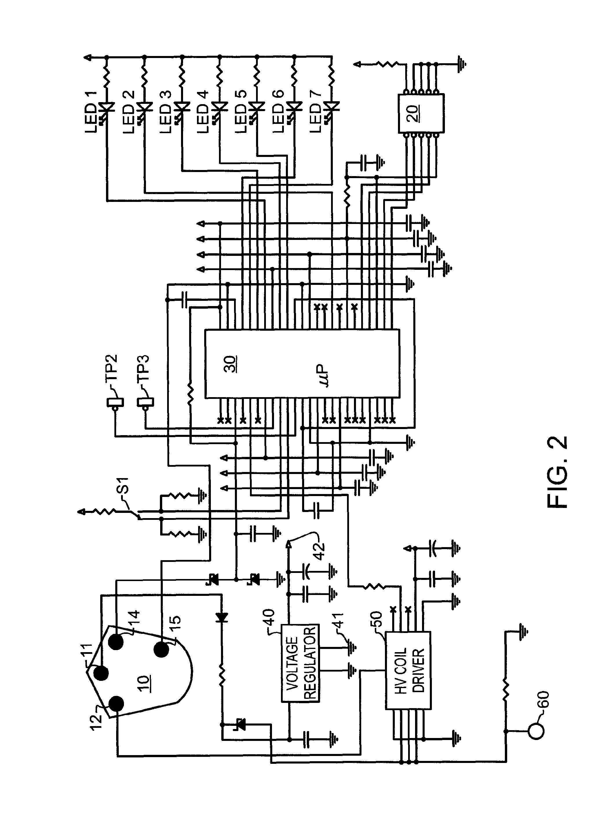
[0023]In a preferred embodiment of the invention illustrated in FIG. 1, a electronic ignition module 1 with rev limiting is comprised of a housing 5 having mounting tabs 2, 3 that provide electrical grounding connection, a TO-3 housed voltage regulator 40 identical in appearance to standard TO-3 housings for stock power transistors mounted externally upon a heat sink 4, and one or more electrical connectors such as ignition connector 10. These features are preferably designed to visually correspond with or preferably identically match stock parts. The model illustrated is a replacement for Chrysler™ or Mopar™ ignition modules, and the components aforementioned are identical to a stock ignition module, though the module in accord with the present teachings may be designed to correspond to or match other makes and parts designs. A bank of Light-Emitting Diodes LED1-LED7 are most preferably provided as visual indicators of the status of the module. Other suitable indicators may be prov...


PUM


Abstract

An ignition control module for an internal combustion engine is incorporated directly into an existing ignition module package design and thereby preserves stock appearance, and is cooperative with stock magnetos, distributors and coils. The module incorporates both ignition pulse generation and adjustable rev limiting. A pushbutton switch allows manual selection of a preferred RPM to rev limit to, and the selection may be carried out under the hood while the engine is running. A plurality of light emitting diodes display the selected rev limit RPM by flashing a corresponding LED, and when not being used to select rev limit RPM, display the engine RPM in bar graph format. A digital flywheel is provided to reduce adverse affect of mechanical jitter in distributor mechanical parts, to improve timing of individual sparks. Dwell and timing curves are programmed into a microprocessor, and may be changed through external input.

Description

CROSS REFERENCE TO RELATED APPLICATIONS[0001]This application claims the benefit of U.S. provisional patent application 61 / 493,978 filed Jun. 6, 2011, the entire contents which are incorporated herein by reference.BACKGROUND OF THE INVENTION[0002]1. Field of the Invention[0003]The present invention relates generally to an ignition control device for an internal combustion piston engine. More particularly, an ignition module having a stock appearance and cooperative with stock magnetos, distributors and coils enables maximum torque and power of the engine while simultaneously controlling a maximum revolution rate.[0004]2. Description of the Related Art[0005]Many drivers of collector cars such as stock antique and classic cars desire to protect, and where possible, improve the performance of their vehicles in an unobtrusive manner, most preferably maintaining the stock appearance not only of the body of the vehicle, but also of the engine compartment as well. Of particular interest to...

Claims


Application Information

Patent Timeline
Patent Type & Authority Patents(United States)
IPC IPC(8): F02P5/145
CPCF02P9/005
Inventor MARTINSON, LAURA J.MARTINSON, TROY P.TITUS, JOHN S.
Owner MARTINSON LAURA J
Learn More