Torque limiter

A technology of torque limiters and components, applied in clutches, couplings, slip couplings, etc., can solve the problems of head flying of shear valves, damage and loss of torque limiters, etc.

Inactive Publication Date: 2014-08-06
JTEKT CORP
View PDF1 Cites 3 Cited by
  • Summary
  • Abstract
  • Description
  • Claims
  • Application Information

AI Technical Summary

Problems solved by technology

[0005] However, in the above-mentioned existing torque limiter, since the head of the shear valve that was cut off at the time of torque release rotates inside the anti-scatter cover, the head of the shear val

Method used


Image

  • Torque limiter
  • Torque limiter
  • Torque limiter

Examples


Embodiment Construction

[0014] Hereinafter, the present invention will be described in detail with reference to the drawings.

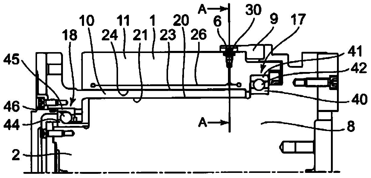
[0015] figure 1 It is a schematic cross-sectional view in the axial direction of the torque limiter according to the first embodiment of the present invention.

[0016] This torque limiter includes a cylindrical member 1 as one member, a shaft member 2 as the other member, four shear valves 6 , ball bearings 17 and ball bearings 18 .

[0017] The above-mentioned cylinder member 1 is composed of a first cylinder member 10 and a second cylinder member 11 . The first cylindrical member 10 has a substantially cylindrical inner peripheral surface 21 that is in contact with the outer peripheral surface 20 of the shaft member 2 . Lubricating oil for preventing seizing exists between the outer peripheral surface 20 of the shaft member 2 and the inner peripheral surface 21 of the first cylinder member 10 . The second cylindrical member 11 has a substantially cylindrical inner peri...


PUM


Abstract

The invention provides a torque limiter. Each shear valve has a head having a generally T shape in a section taken along the radial direction of a shaft member and projected from a tubular member when the shear valve is fixed in a shear valve fitting hole. The shaft member has at least one generally T-shaped groove that has a shape corresponding to the shape of the head in the section and that accommodates the head during torque transmission.

Description

technical field [0001] The present invention relates to torque limiters. Background technique [0002] Conventionally, as a torque limiter, it is described in Japanese Unexamined Patent Application Publication No. 2009-293680. In this torque limiter, the inner peripheral surface of the cylindrical member is fitted on the outer peripheral surface of the shaft member, and pressure oil is supplied to the hydraulic expansion chamber of the cylindrical member, and the inner circumference of the cylindrical member is reduced by the pressure oil in the hydraulic expansion chamber. The diameter of the face. Then, the inner peripheral surface of the cylindrical member is pressed against the outer peripheral surface of the shaft member, and the shaft member and the cylindrical member are frictionally coupled to transmit torque. Further, the shear valve is used to seal the pressure oil in the hydraulic expansion chamber, and on the other hand, a locking member locked to an end portio...

Claims


Application Information

Patent Timeline
IPC IPC(8): F16D7/02
CPCF16D1/0805F16D9/06F16D7/021F16D43/286
Inventor 北条裕纪
Owner JTEKT CORP
Why Eureka
Try Eureka