Engine revolution limiter

a technology of revolution limiter and engine, which is applied in the direction of speed sensing governor, machine/engine, ignition safety means, etc., can solve the problems of limited ignition firing, increased limit to 5,000 rpm, and insufficient limiting of engine speed by limiting ignition firing, etc., to achieve improved control, reduce engine speed, and increase engine speed

Inactive Publication Date: 2005-11-15
S&S CYCLE INC
View PDF12 Cites 3 Cited by
  • Summary
  • Abstract
  • Description
  • Claims
  • Application Information

AI Technical Summary

Benefits of technology

[0012]In addition, the revolution limiter system may be modified so that the controller has an over-revolution limit that is greater than the revolution limit. A typical over-revolution limit might be approximately 256 RPM higher than the associated revolution limit. If the system's engine speed monitor determines that the revolution limit has been exceeded, it compares engine speed to the over-revolution limit, to determine whether it has been exceeded. If the over-revolution limit is exceeded, the firing to the ignition stops altogether until it is determined by the engine speed monitor that the engine speed is below the over-revolution limit. It can be appreciated that in some circumstances such as a vehicle going down hill, that limiting ignition firing may not slow down the engine sufficiently and engine speed may remain at an increased level. Therefore, the additional over-revolution limit is added. The system has advantages in that the engine operator will notice when the revolution limit is exceeded by the stuttering noise of the engine and will usually make manual adjustments to lower engine speed. This also provides for power from the engine for longer periods, giving the operator better control. However, if the revolution limiting is not sufficient to slow the engine, then the ignition firing stops. It is foreseen that if the operator is correctly operating the engine, the over-revolution limit should rarely be exceeded as the operator may manually limit operating speed once stuttering is detected.

Problems solved by technology

For example, during an initial eight hour break-in period, if an engine speed exceeds 4,000 RPM, ignition firing is limited.
In addition, an over-revolution speed level may also be selected that is higher than the maximum speed level in case of emergencies wherein limiting engine speed by limiting firing of the ignition is not sufficient.
However, a second period extending through sixteen hours of engine operating time may raise the limit to 5,000 RPM.
If the engine speed exceeds the revolution limit, ignition firing is limited.
The engine still has power, but with stuttering, tends to slow down from the limited firing of the ignition.
However, if the revolution limiting is not sufficient to slow the engine, then the ignition firing stops.

Method used


Image

  • Engine revolution limiter
  • Engine revolution limiter
  • Engine revolution limiter

Examples


first embodiment

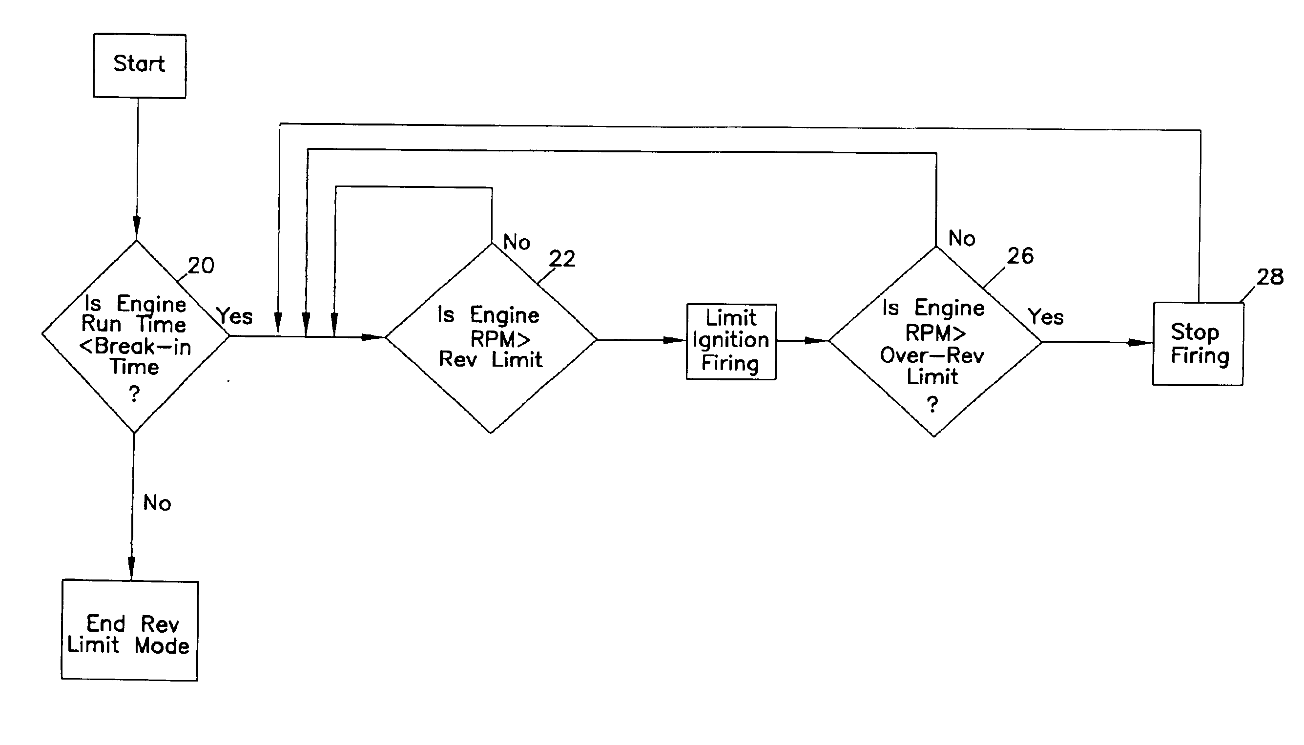
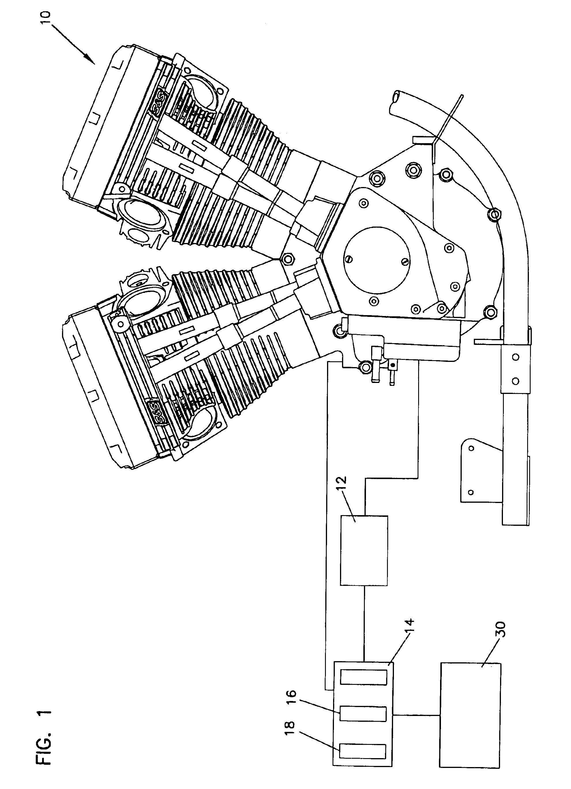
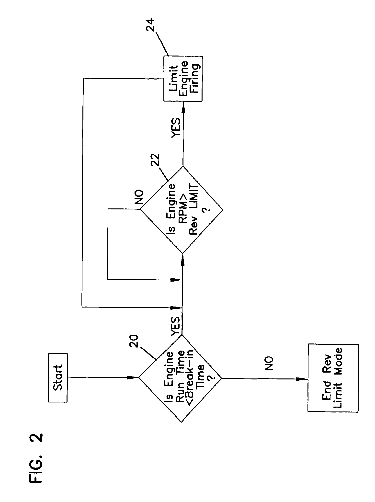
[0025]Referring now to FIGS. 1 and 2, there is shown the control system 14. Upon startup, the engine control system utilizes the time monitor 18 to determine whether the engine operating time is less than the predetermined break-in period at step 20 of FIG. 2. If the operating time is less than the break-in period, then the engine speed monitor 16 checks to measure engine speed at step 22. If the engine speed is greater than the preset revolution limit, firing of the ignition is limited as at step 24. The engine speed is continually monitored as at step 22. Limiting of the firing of the ignition at step 24 has the effect of slowing down the engine speed so that it is anticipated that engine speed will fall back below the predetermined limit quickly in most operating conditions.

[0026]In a preferred embodiment, once the revolution limit is exceeded and firing of the ignition is limited as at step 24, a particular firing sequence is engaged. In one embodiment, the engine ignition is fi...

third embodiment

[0028]Referring to FIG. 4, there is shown the present invention. As in FIG. 2, the engine run time is monitored at step 20, the engine speed is monitored at step 22 and ignition firing is limited at step 24. However, multiple break-in periods and corresponding engine revolution limits are programmed, and additional monitoring takes place at steps 120 and 122. For example, if a second break-in period T2 has been programmed at step 120, the period will be monitored after an initial break-in period expires. If the corresponding engine revolution limit, as represented by L2, has been exceeded, as detected by monitoring at step 122 in FIG. 4, engine ignition firing is limited at step 124 and stuttering occurs.

[0029]If the first and second break-in periods have expired, the control system 14 checks to see whether a third break-in period, or additional periods as represented by TN, have been set. If the engine run time is less than the break-in period TN, the monitoring system 14 compares ...


PUM


Abstract

An engine revolution limiter system is utilized to limit engine speed during a break-in period. The system provides for programming a variable break-in period and a variable selectable engine revolution limit. During the break-in period, if the revolution limit is exceeded by the engine speed, firing of the ignition is limited. In addition, the system provides for an over revolution limit wherein the ignition stops firing if the over revolution limit is exceeded. In addition, multiple break-in periods may be programmed with different associated revolution limits and over revolution limits. This provides for gradually increasing the allowable engine speed as the engine has been operating for greater periods of time.

Description

BACKGROUND OF THE INVENTION[0001]1. Field of the Invention[0002]The present invention relates to an internal combustion engine revolution limiting apparatus, and in particular to a system and method for limiting maximum engine revolutions during a break-in period.[0003]2. Description of the Prior Art[0004]It is often recommended with internal combustion engines to limit the engine operating speed during an initial break-in period. Limiting the operating speed places less stress on the engine initially and allows components to seat relative to one another. Engine components operate without undue stress that might otherwise damage some of the components.[0005]In the past, such limiting of engine speed was accomplished by simply informing operators that the engine should be operated at or below certain engine speed limits for specified initial time periods. However, an owner of a new vehicle often wants to test its speed and acceleration. The recommendations are ignored and damage to t...

Claims


Application Information

Patent Timeline
Patent Type & Authority Patents(United States)
IPC IPC(8): F02D31/00F02P11/00F02P11/02F02P9/00
CPCF02P9/005F02P11/02
Inventor GUDGEON, JOSEPH A.HILLEGASS, NEVIN R.LINDELL, BRIAN S.
Owner S&S CYCLE INC
Why Eureka
Try Eureka