
Radio communication apparatus used in CDMA communication system, which has fingers and is designed to perform rake reception, and power consumption control method therefor

a technology of cdma communication system and radio communication apparatus, which is applied in the direction of multiplex communication, wireless communication, power management, etc., can solve the problems of increasing power consumption, demodulation failure, and wasting power, and achieve good reception quality and reduce power consumption

Inactive Publication Date: 2005-06-14
LENOVO INNOVATIONS LTD HONG KONG
View PDF13 Cites 9 Cited by
  • Summary
  • Abstract
  • Description
  • Claims
  • Application Information

AI Technical Summary

Benefits of technology

The present invention provides a radio communication apparatus and method for CDMA communication systems that reduces power consumption while maintaining good reception quality. The apparatus includes a delay profile calculating section for calculating a delay profile using a reception signal, a finger path allocating section for operating the fingers on the basis of the delay profile, a rake reception section for combining despreading results from the plurality of fingers, and a delay profile calculation control section for controlling the delay profile calculating section based on the reception characteristics detected by a reception characteristic detecting section. The delay profile calculating section calculates the delay profile using a predetermined number of calculations, while the finger path allocating section assigns path positions to the plurality of fingers based on the delay profile. The delay profile calculation control section controls the number of calculations based on the reception characteristics detected by the reception characteristic detecting section. The apparatus also includes a known data table and a threshold table for comparing the error rate of the reception signal with a threshold to determine the quality of the reception. The delay profile calculation control section controls the operation of the delay profile calculating section based on the output from the reception data comparing section. The technical effects of the invention include reducing power consumption while maintaining good reception quality, improving the efficiency of the radio communication apparatus, and optimizing the allocation of resources for CDMA communication systems.

Problems solved by technology

For this reason, in the conventional demodulation circuit, delay profile calculation is performed even when it is not necessary, resulting in a waste of power.
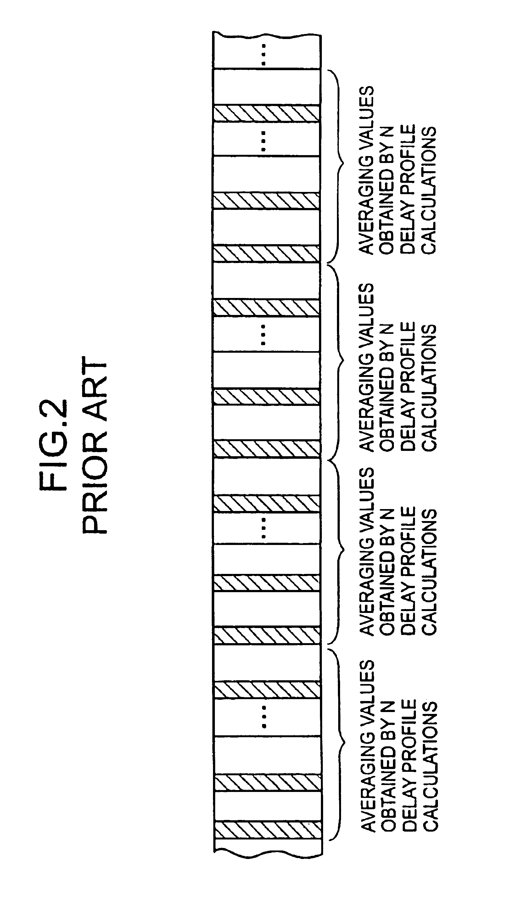
If the intervals at which delay profile calculation is performed are simply prolonged to reduce power consumption, delay profile calculation may not be performed even when it is necessary as the effective reception path position changes, resulting in a demodulation failure.
As communication terminals, like current portable telephone terminals, are required to become smaller in size with longer periods of use, increases in power consumption pose a serious problem.

Method used


Image

  • Radio communication apparatus used in CDMA communication system, which has fingers and is designed to perform rake reception, and power consumption control method therefor
  • Radio communication apparatus used in CDMA communication system, which has fingers and is designed to perform rake reception, and power consumption control method therefor
  • Radio communication apparatus used in CDMA communication system, which has fingers and is designed to perform rake reception, and power consumption control method therefor

Examples


first embodiment

[0089]FIG. 8 is a block diagram showing a demodulation circuit which performs demodulation by despreading and serves as a radio communication apparatus according to the present invention in a CDMA mobile station.

[0090]Referring to FIG. 8, this demodulation circuit is comprised of a delay profile calculating section 20 for calculating a delay profile, a finger path allocating section 12 for operating fingers 13a and 13b on the basis of the delay profile generated by the delay profile calculating section 20, a finger section 13 constituted by the fingers 13a and 13b for despreading reception signals, a rake reception section 14 for combining the despreading results as the outputs from the fingers 13a and 13b, a reception data processing section 15 for demodulating the output from the rake reception section 14 and outputting the resultant digital data as a demodulated output signal, a reception characteristic detection unit constituted by a known data table 16 in which known data (e.g....

second embodiment

[0126]the present invention will be described next.

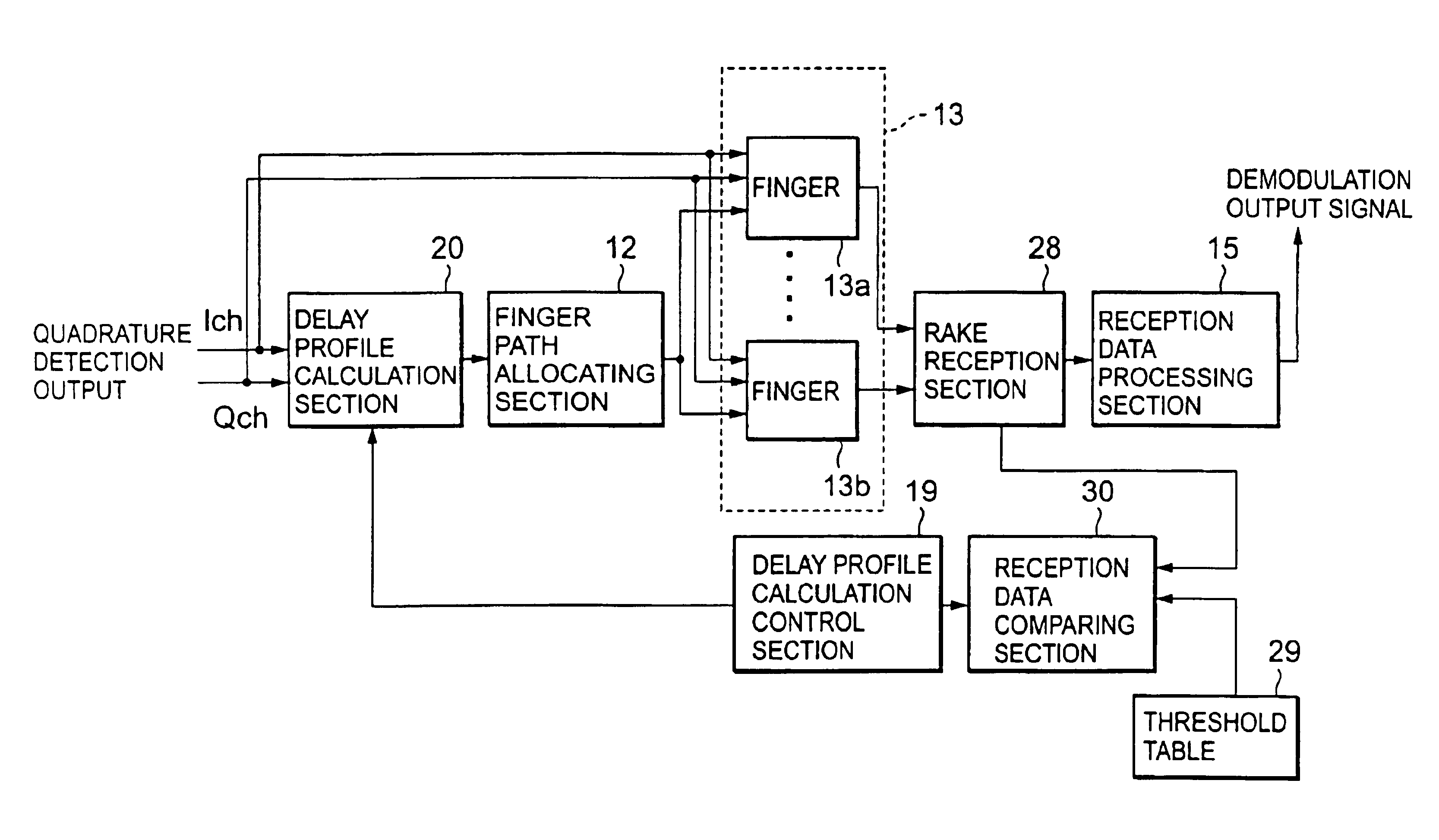
[0127]FIG. 13 is a block diagram showing the second embodiment of a demodulation circuit which performs demodulation by despreading and serves as a radio communication apparatus according to the present invention in a CDMA mobile station.

[0128]Referring to FIG. 13, this demodulation circuit is comprised of a delay profile calculating section 20 for calculating a delay profile, a finger path allocating section 12 for operating fingers 13a and 13b on the basis of the delay profile generated by the delay profile calculating section 20, a finger section 13 constituted by the fingers 13a and 13b for despreading reception signals, a rake reception section 28 for combining the despreading results as the outputs from the fingers 13a and 13b, outputting the resultant data, and estimating and outputting a reception SIR (Signal to Interference Ratio), a reception data processing section 15 for demodulating the output from the rake reception se...

third embodiment

[0141]the present invention will be described next.

[0142]FIG. 15 is a block diagram showing the third embodiment of a demodulation circuit which performs demodulation by despreading and serves as a radio communication apparatus according to the present invention in a CDMA mobile station.

[0143]The same reference numerals as in FIG. 8 denote the same parts in FIG. 15, and a detailed description thereof will be omitted.

[0144]In the third embodiment, a delay profile calculating section 20 has the same internal arrangement as that shown in FIG. 9, and hence will be described with reference to FIG. 9.

[0145]According to the reception characteristic detection function of the third embodiment, a first threshold and a second threshold lower than the first threshold are stored in a threshold table 17a in FIG. 15 in advance. A reception data comparing section 18 outputs a first reception good signal when a reception BER is equal to or lower than the first threshold, and outputs a second recepti...


PUM


Abstract

A radio communication apparatus which is used in a CDMA communication system, has a plurality of fingers, and performs rake reception, includes a delay profile calculating section and a finger path allocating section. The delay profile calculating section calculates a delay profile using a reception signal. The finger path allocating section allocates path positions to the plurality of fingers on the basis of the delay profile calculated by the delay profile calculating section. A delay profile calculation cycle in the delay profile calculating section is variable. A power consumption control method is also disclosed.

Description

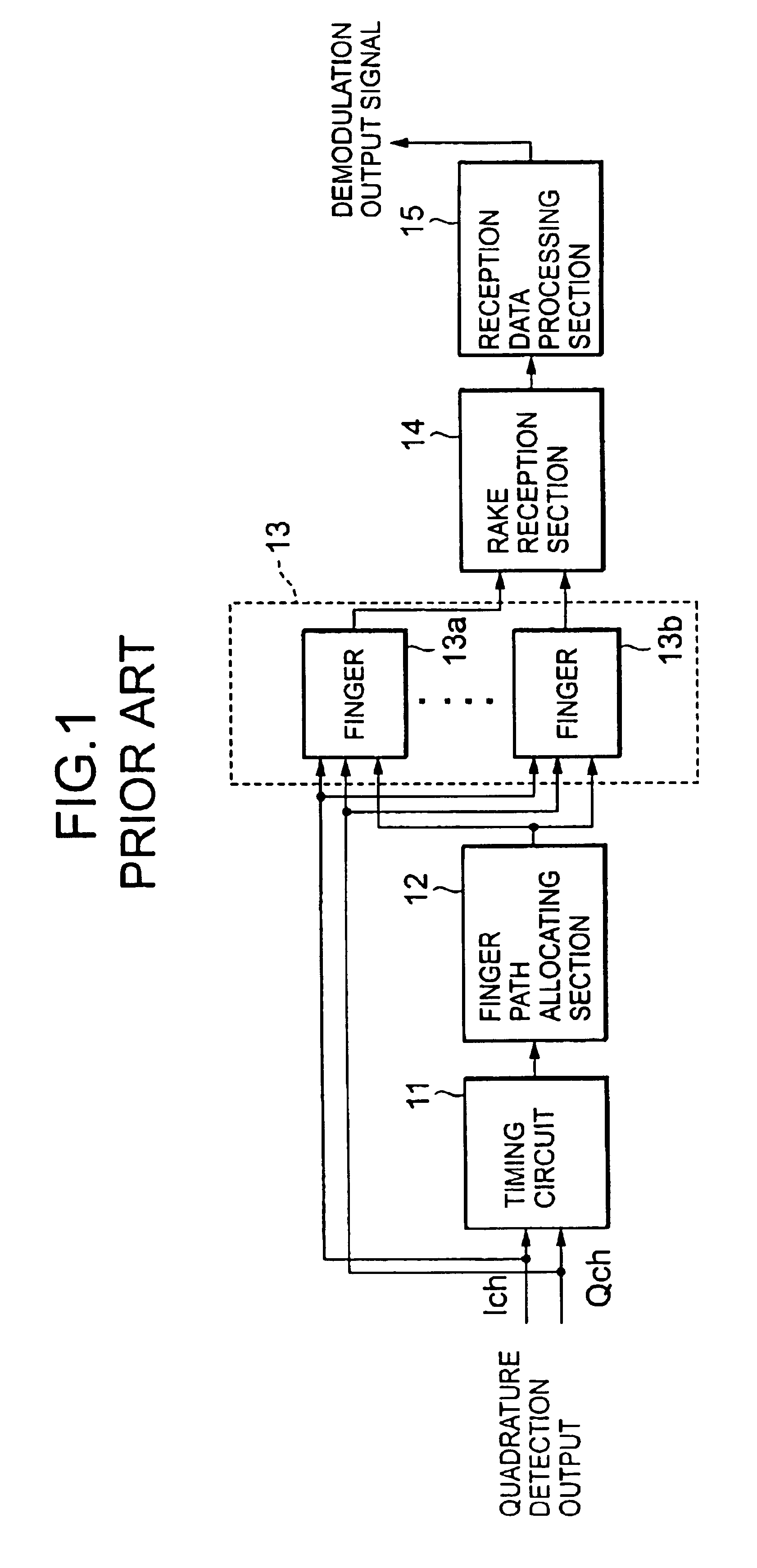
BACKGROUND OF THE INVENTION[0001]1. Field of the Invention[0002]The present invention relates to a radio communication apparatus and a power consumption control method therefor and, more specifically, to a radio communication apparatus used in a CDMA mobile communication system, which has a plurality of fingers and is desired to perform rake reception, and a power consumption control method therefor.[0003]2. Description of the Prior Art[0004]Recently, mobile communication systems such as a system using portable telephones have become widespread. One of the communication schemes used by such mobile communication systems is CDMA (Code Division Multiple Access).[0005]According to CDMA, on the transmitting side, data is spread by using one of predetermined spreading codes which differ depending on the data to be transmitted, and the spread data is transmitted. On the receiving side, the data is obtained by spreading (so-called despreading) the reception signal by using a spreading code ...

Claims


Application Information

Patent Timeline
Patent Type & Authority Patents(United States)
IPC IPC(8): H04B1/707H04B1/7075H04B1/7113H04B1/7115H04B1/7117H04B7/02H04B7/26H04W16/28H04W52/02
CPCH04B1/70752H04B1/7113H04B1/7117H04B1/7115H04B2201/70707
Inventor TAMURA, KOICHI
Owner LENOVO INNOVATIONS LTD HONG KONG
Learn More