Impedance matched horn having impedance matched to impedance of an ear

a technology of impedance matching and horn, which is applied in the field of impedance matching horn, can solve the problems of limiting the size, weight and type of equipment that can the features available in the larger receiver system such as loudspeakers and conventional telephones are not adapted to be used in the receiver of radiotelephone, so as to achieve the effect of reducing size and weigh

Inactive Publication Date: 2005-06-14
OPTIS WIRELESS TECH LLC
View PDF9 Cites 13 Cited by
  • Summary
  • Abstract
  • Description
  • Claims
  • Application Information

AI Technical Summary

Benefits of technology

[0002]Typically, radiotelephones include a main body having a receiver or speaker housed in an upper portion thereof and oriented to direct sound directly through an outer housing into the user's ear. The overall quality of speech and sound emitted by the receiver of a radiotelephone is sometimes referred to as speech intelligibility. It is an objective in devices such as radiotelephones to minimize size and weight without compromising speech intelligibility.
[0004]Factors such as interference from electrical components in radiotelephones presents restrictions on the design of receivers. U.S. Pat. No. 5,963,640, the disclosure of which is incorporated by reference, discloses the use of an acoustical waveguide coupled to a speaker to permit mounting of the speaker at a point remote from sound ports that are intended to be placed proximate a user's ear and thus increase design flexibility. Nonetheless, receivers are designed in view of the impedance of free air, certain design features available in larger receiver systems such as loudspeakers and conventional telephones are not adapted to be used in receivers for radiotelephones. The impedance of free air necessitates that large volumes of air be moved to generate sufficiently intelligible sound. Accordingly, relatively large drivers are necessary to match the impedance of free air. This, in turn, presents limits in terms of the size, weight, and type of equipment that can be used, and how and where it can be located in a radiotelephone.
[0006]The present invention solves problems associated with prior art systems through the inventor's recognition that impedance of free air is not necessarily an appropriate design factor for consideration in radiotelephones. More particularly, the present invention relates to the inventor's discovery that, in receivers, it may be appropriate to match impedance of a horn to impedance of the driver and impedance of a user's ear instead of matching impedance to impedance of free air. This discovery results in permitting substantially smaller impedance matched horns and drivers than were previously known. Because the size of receivers including drivers and impedance matched horns can be substantially reduced according to the present invention, radiotelephone design flexibility is substantially improved, as the receivers are more easily isolated from potentially interference-using components, and the weight and size of radiotelephones can be reduced. Further, speech intelligibility need not be compromised and may be enhanced through the use of a receiver including a horn having impedance matched with the impedance of an ear.

Problems solved by technology

Factors such as interference from electrical components in radiotelephones presents restrictions on the design of receivers.
Nonetheless, receivers are designed in view of the impedance of free air, certain design features available in larger receiver systems such as loudspeakers and conventional telephones are not adapted to be used in receivers for radiotelephones.
This, in turn, presents limits in terms of the size, weight, and type of equipment that can be used, and how and where it can be located in a radiotelephone.
For example, although impedance matched horns matched to the impedance of the driver and free air are quite effectively used in large systems, the impedance of air requires such horns to be of sizes too great for use in smaller devices such as radiotelephone receivers.
However, such a horn and transducer would be of substantial size, just like the disclosed horn and microphone.

Method used


Image

  • Impedance matched horn having impedance matched to impedance of an ear
  • Impedance matched horn having impedance matched to impedance of an ear

Examples


Embodiment Construction

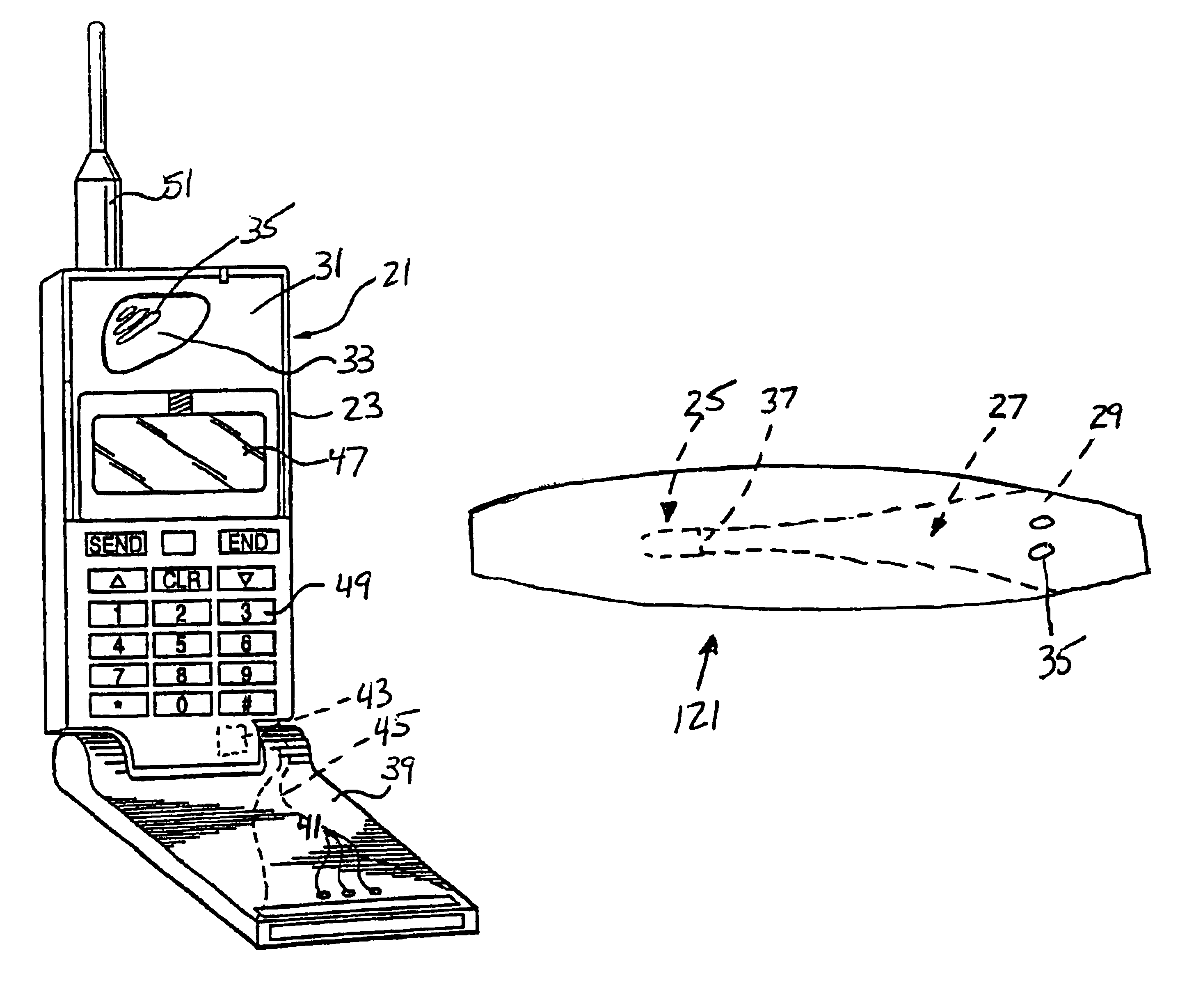
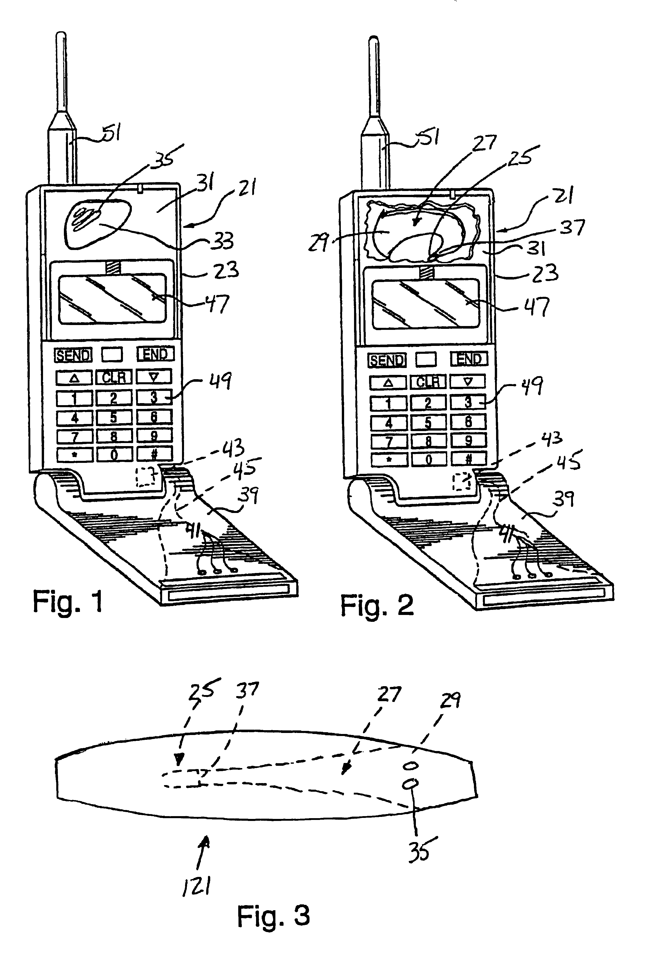
[0015]A portable device 21 according to an embodiment of the present invention is shown in FIGS. 1 and 2. The device 21 includes a body 23, a driver 25 mounted inside the body, and an acoustic horn 27. The horn 27 has an acoustical impedance matched with impedances of an ear and the driver 25. A large end 29 of the horn 27 extends to a position proximate an exterior surface 31 of the body 23. A plate 33, which is preferably simply part of the body 23, is preferably disposed proximate the large end 29 of the horn 27 and has one or more, preferably a plurality of holes 35 therein. The plate 33 assists in preventing external objects from being inserted in or falling into the horn 27. The horn 27 may be separate from the body 23 or may be integrally formed with the body, such as by being formed upon molding of a plastic body.

[0016]The driver 25 preferably includes a driving membrane 37. The driver 25 is preferably quite small, preferably on the order of 2 mm×1 mm×5 mm overall, although ...


PUM


Abstract

An acoustic horn has an acoustic impedance matched with impedances of an ear and a driver. The acoustic horn can be used in an electroacoustic transducer including the driver, and the acoustic horn. The electroacoustic transducer is particularly well-suited for use in portable device such as a radiotelephone, pager, or other device.

Description

TECHNICAL FIELD OF THE INVENTION[0001]The present invention relates to an impedance matched horn and, more particularly, to an impedance matched horn having an impedance matched to an impedance of an ear.BACKGROUND AND SUMMARY[0002]Typically, radiotelephones include a main body having a receiver or speaker housed in an upper portion thereof and oriented to direct sound directly through an outer housing into the user's ear. The overall quality of speech and sound emitted by the receiver of a radiotelephone is sometimes referred to as speech intelligibility. It is an objective in devices such as radiotelephones to minimize size and weight without compromising speech intelligibility.[0003]Speech intelligibility in radiotelephones is generally affected by a number of design factors including the receiver design, how and where the receiver is housed, and how the emitted sound energy is channeled to the ear. Ideally, a radiotelephone should produce a fairly level frequency response for a ...

Claims


Application Information

Patent Timeline
Patent Type & Authority Patents(United States)
IPC IPC(8): H04M1/03H04R1/28H04M1/02
CPCH04R1/30H04M1/03H04M1/0214H04R2499/11
Inventor ANDERSSON, JONAS
Owner OPTIS WIRELESS TECH LLC
Why Eureka
Try Eureka