Power transmission mechanism and electric drive system using the same

a transmission mechanism and electric drive technology, applied in the direction of interengaging clutches, road transportation, fluid couplings, etc., can solve the problems of affecting the safety of the motor, the collision between the driving and the driven members may not mesh with each other, and the locking of the motor and the driven members may fail to work properly, so as to minimize the drag torque, improve fuel economy, and protect the motor.

Inactive Publication Date: 2006-09-12
NTN CORP
View PDF9 Cites 7 Cited by
  • Summary
  • Abstract
  • Description
  • Claims
  • Application Information

AI Technical Summary

Benefits of technology

[0012]The two-way clutch can be easily engaged and disengaged simply by energizing and deenergizing the electromagnet of the electromagnetic clutch. The two-way clutch can completely shut off transmission of torque between the driving member and the driven member when it is disengaged. Since the rollers are provided in a plurality of rows, the contact area between the rollers and the inner and outer members of the clutch increases and thus the maximum torque that can be transmitted through the rollers increases without the need to change the dimensions of each roller or the number of rollers in each row.
[0025]Each of the power transmission mechanism is preferably integral with the corresponding hub bearing. This minimizes the size and weight of the entire system.

Problems solved by technology

Otherwise, the claws of the driving and driven members may fail to mesh with each other and / or shock may be produced when they are meshed with each other.
Even if the claws are meshed with each other, they may be locked together due to torque resulting from friction in the motor.
Once they are locked together, they may not easily separate from each other even when trials are made to disengage the clutch after the motor has been stopped.
But it has another problem in that even when the clutch is disengaged, the driving member and the driven member cannot be completely separated from each other due to the presence of viscous fluid in the clutch.
Thus, even when the clutch is disengaged, torque may be transmitted from the wheels to the motor, thus overloading the motor.
Thus, such a clutch cannot sufficiently protect the motor.
This worsens fuel economy.
Such a friction clutch is inevitably large in size and heavy in weight, and thus further worsens fuel economy.
If such clutch assemblies protrude from the outboard ends of the respective hub bearings, they will pose safety problems and ruin the appearance of the vehicle.
If they protrude from the inboard ends of the hub bearings, they will interfere with driving members such as constant-velocity joints, thus restricting the freedom of design of these members.
Thus, the maximum torque that can be transmitted through such small-diameter rollers is also small.
This increases the possibility of malfunction of the clutch.
Specifically, this increases the possibility of the rollers inadvertently engaging or disengaging when the retainer rotates even slightly relative to the driving member due to vibrations or shocks.
This increases the cost for forming the cam surfaces and also makes it more difficult to form the cam surfaces.
If longer rollers are used to increase the contact area, the rollers are more likely to inadvertently engage or disengage when the inner and outer members of the clutch deflect due e.g. to impulse loads that act on the wheel and as a result, the shape of the gap between the inner and outer members changes.

Method used


Image

  • Power transmission mechanism and electric drive system using the same
  • Power transmission mechanism and electric drive system using the same
  • Power transmission mechanism and electric drive system using the same

Examples


Embodiment Construction

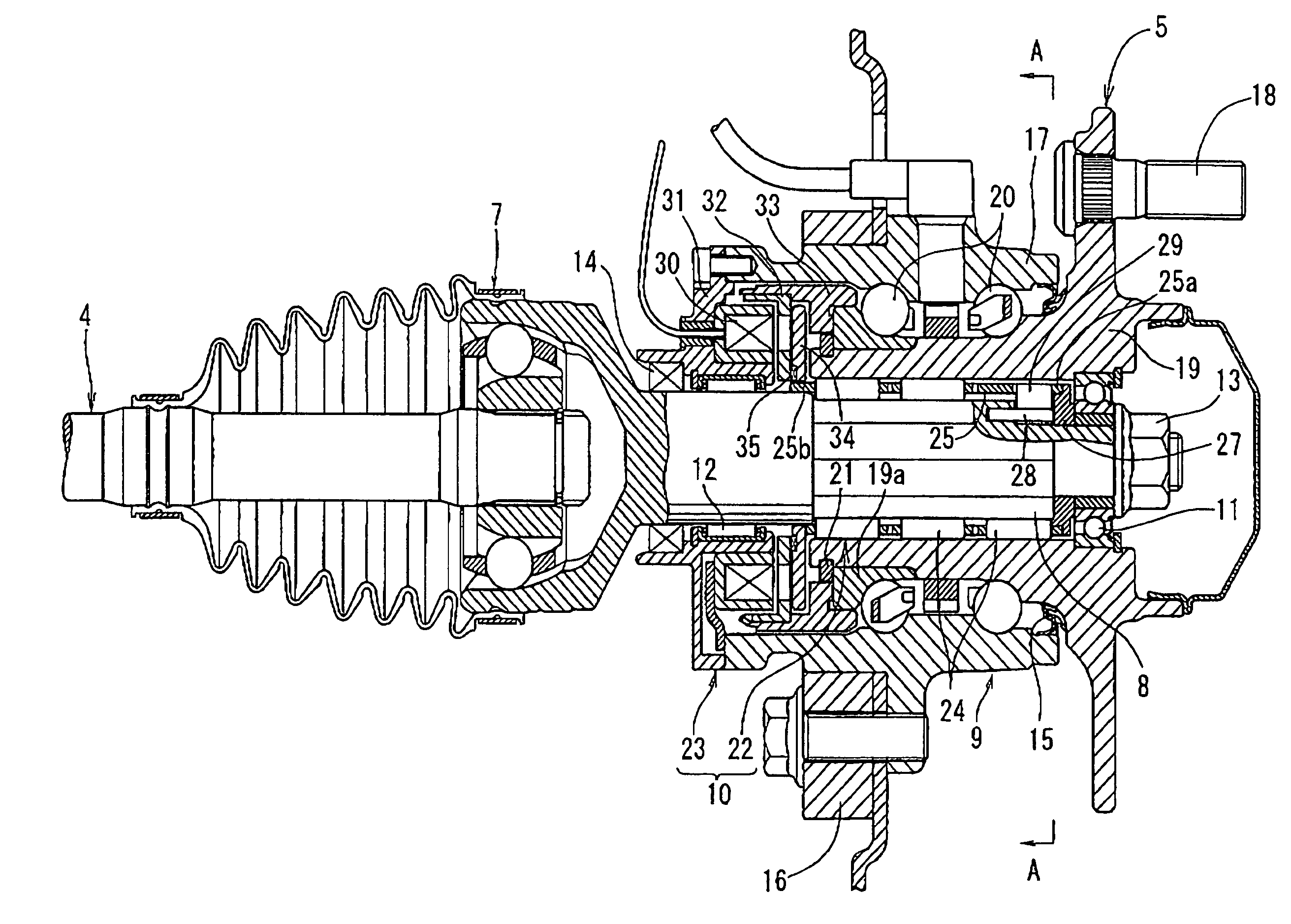
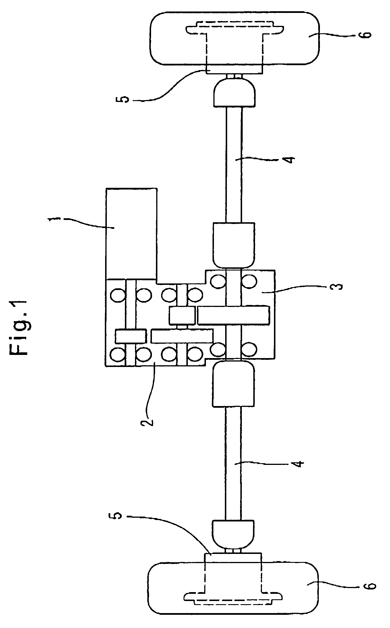
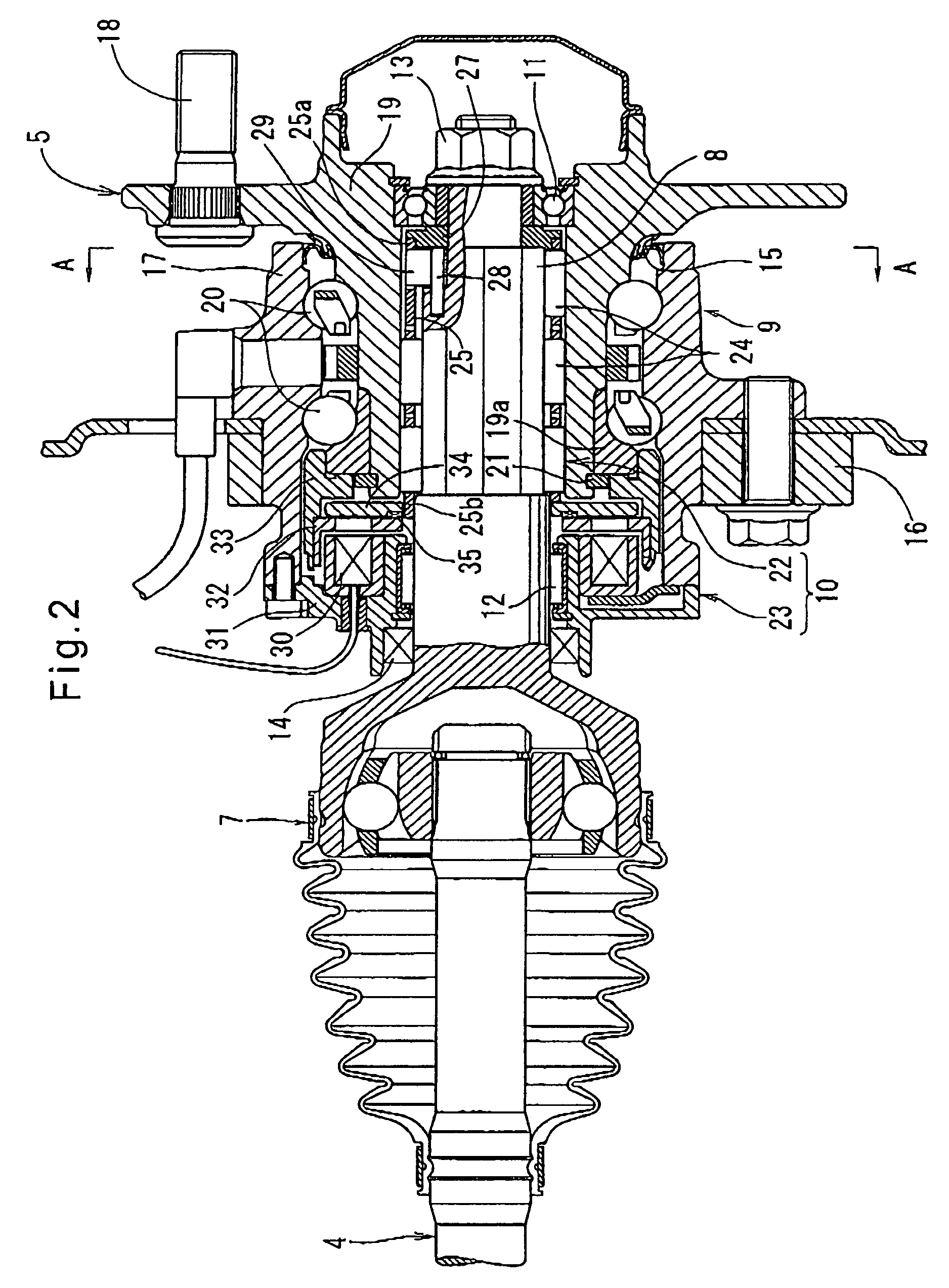
[0032]Now referring to FIGS. 1–7, the electric drive system embodying the present invention will be described below. This drive system is mounted on what is known as a hybrid car to drive either its front or rear wheels, and includes an electric motor 1 and a drive train. The driving torque produced by the electric motor 1 is transmitted to right and left wheels 6 through the drive train, which comprises a speed reducer 2, a power distribution mechanism 3, drive axles 4, and power transmission mechanisms in hub clutch units 5.

[0033]The electric motor 1 is a DC motor including a permanent magnet. Its output (rotation) is reduced in speed by the speed reducer 2 and delivered to the right and left drive axles 4 through the power distribution mechanism 3. The outputs of the respective drive axles 4 are delivered to the respective wheels 6 through the respective hub clutch units 5. The wheels 6 thus rotate at the same speed as long as the hub clutch units 5 are both engaged.

[0034]As show...


PUM


Abstract

A power transmission mechanism for a vehicle includes a clutch assembly which includes a two-way clutch and an electromagnetic clutch. The two-way clutch includes three rows of rollers retained by a retainer and disposed between a clutch inner member, which is actually a stem of a constant-velocity joint mounted on the outboard end of a drive axle, and a clutch outer member, which is actually a hub ring of a hub bearing supporting a vehicle wheel. Simply by energizing and deenergizing the electromagnet of the electromagnetic clutch, the two-way clutch can be engaged and disengaged. Since the rollers are arranged in three rows, it is possible to increase the contact area between the rollers and the clutch inner and outer members and thus the maximum torque that can be transmitted through the rollers without the need to increase the number of rollers in each row or their length or diameter.

Description

BACKGROUND OF THE INVENTION[0001]This invention relates to a power transmission mechanism mounted on a vehicle for transmitting driving torque to a wheel of the vehicle, and an electric drive system including two such power transmission mechanisms for driving at least the front wheels or the rear wheels of a vehicle.[0002]Because of their environment-friendliness, electric vehicles, which run on an electric motor alone, and hybrid cars, which use both a conventional internal combustion engine and an electric motor, are now being vigorously developed by many car manufacturers. Some of them are already hitting the market. The electric drive system of this type of vehicles has a power transmission mechanism in its drive train. Such a power transmission mechanism includes a clutch for selectively allowing and shutting off torque transmission between the driving motor and wheels to protect the motor against overloads from the wheels or prevent accidents due to runaway of the motor. Conve...

Claims


Application Information

Patent Timeline
Patent Type & Authority Patents(United States)
IPC IPC(8): B60K17/02F16D15/00B60K7/00F16D27/118F16D41/08
CPCB60K17/02F16D41/088F16D27/118B60K2001/001Y02T10/76
Inventor TAKASHI, NOZAKIAKIRA, YAMAGATAHIROYUKI, HAKAMATAYOSHIHIKO, HAYAMA
Owner NTN CORP
Why Eureka
Try Eureka