Beacon docking system with visual guidance display

a technology of visual guidance and beam docking system, which is applied in the direction of bridges, ground installations, constructions, etc., can solve the problems of time-consuming image processing, slow movement based thereon, and inconvenience for passengers waiting on board the aircra

Inactive Publication Date: 2005-06-21
AMERIBRIDGE
View PDF8 Cites 31 Cited by
  • Summary
  • Abstract
  • Description
  • Claims
  • Application Information

AI Technical Summary

Problems solved by technology

Unfortunately, the bridge-operator must be present to press a switch for enabling the automated height adjustment.
As such, the bridge-operator must arrive at the passenger loading bridge in advance of the aircraft, which wastes the time of the bridge-operator, or alternatively the bridge-operator initiates the height adjustment after the aircraft has arrived at the passenger loading bridge, which inconveniences the passengers that are waiting on board the aircraft.
However, image-processing is time-consuming, thus making the movement based thereon slow.
Unfortunately, the local computer must be in communication with a flight information database of the airport terminal building in order to receive information relating to the type or model of aircraft that is approaching the gate.
Such a database must be set up to be accessible by the local computer, and there may be serious security-related issues involved with providing widely distributed access to sensitive flight information.
Furthermore, many airports around the world do not support databases that would be suitable for interfacing with a passenger loading bridge system as described by Anderberg.
It is a disadvantage of the prior art manual, semi-automated and automated bridge alignment systems that the alignment operation is performed on the basis of observations that are made from a location that is remote to the aircraft.
If such observations are erroneous, then the bridge may be allowed to collide unintentionally with the aircraft.
Of course, adverse environmental conditions, such as snow, fog, darkness, etc., will greatly increase the likelihood of an erroneous observation.

Method used


Image

  • Beacon docking system with visual guidance display
  • Beacon docking system with visual guidance display
  • Beacon docking system with visual guidance display

Examples


first embodiment

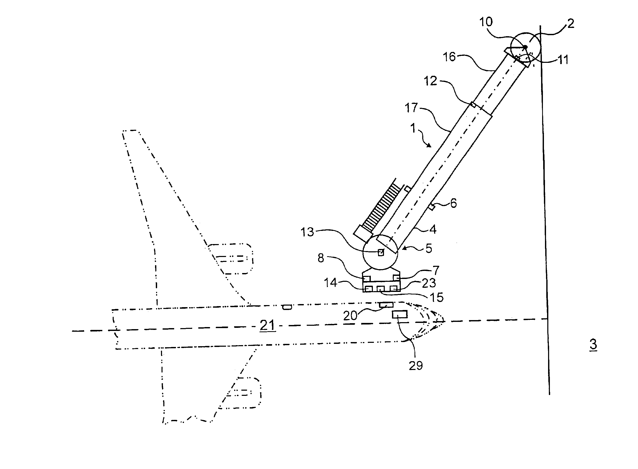
[0061]Referring to FIG. 1, shown is a system according to the instant invention. An aircraft 21 having a doorway 20 is equipped with a transmitter unit 29 for transmitting one of an optical signal and a radio frequency (rf) signal. Preferably, the transmitter unit 29 is disposed within a window (not shown) of the doorway 20 to which a passenger boarding bridge 1 is to be connected.

[0062]Also illustrated in FIG. 1 is the passenger boarding bridge 1, for instance an apron drive bridge including a rotunda 2 that is connected to a terminal building 3 and from which extends a passageway 4. The passageway 4 ends with a pivotable cabin 5 and includes inner passageway element 16 and outer passageway element 17, wherein the inner passageway element 16 is telescopically received within the outer passageway element 17 such that the length of the passageway 4 is variable. Each passageway element 16,17 includes a left sidewall, a right sidewall, a floor member and a ceiling member. Optionally, a...

second embodiment

[0073]Referring to FIG. 3, shown is a system according to the instant invention. Elements labeled with the same numerals have the same function as those illustrated in FIG. 1. An aircraft 21 having a doorway 20 is equipped with a transmitter unit 39 for transmitting one of an optical signal and a radio frequency (rf) signal. Preferably, the transmitter unit 39 is disposed within a window (not shown) of the doorway 20 to which a passenger boarding bridge 1 is to be connected. The passenger boarding bridge 1 includes a receiver unit 33 fixedly mounted near the cabin end of the passenger boarding bridge 1, for receiving the one of an optical signal and a radio frequency (rf) signal emitted by transmitter unit 39 of the aircraft 21. The signal is emitted by the transmitter unit 39 of the aircraft 21 to “call” for the passenger boarding bridge 1 when the aircraft 21 is parked at the gate area adjacent the passenger boarding bridge 1. Preferably, the signal is also used to guide the cabin...

third embodiment

[0085]Referring now to FIG. 7, shown is a system according to the instant invention. Elements labeled with the same numerals have the same function as those illustrated in FIG. 1. Aircraft 21 includes a transceiver 22 for transmitting one of an optical signal and an RF signal and for receiving one of an optical signal and an RF signal. Preferably, the transceiver 22 is disposed within a window (not shown) of the doorway 20 to which a passenger boarding bridge 1 is to be connected. The transceiver 22 is used only during the aircraft docking and passenger boarding bridge alignment operations. Passenger boarding bridge 1 includes a transceiver 24, for receiving the one of an optical signal and an RF signal transmitted from the aircraft 21 and for transmitting the one of an optical signal and an RF signal to be received by the transceiver 22 of aircraft 21. Accordingly, two-way communication occurs between the aircraft 21 and the passenger boarding bridge 1, which permits the implementa...


PUM


Abstract

Disclosed is a system and method for automatically aligning an end of a passenger boarding bridge with a doorway of an aircraft. A beacon is transmitted from a predetermined location aboard the aircraft, such as within a window proximate a doorway of the aircraft. The beacon is sensed and from the sensed beacon a direction for moving of the end of the passenger boarding bridge is determined. The passenger boarding bridge is then moved according to the determined direction. The process is iterated until the docking of the bridge to the aircraft is completed.

Description

[0001]This application is a continuation-in-part of U.S. patent application Ser. No. 10 / 139,376 filed May 07, 2002. now U.S. Pat. No. 6,637,063.FIELD OF THE INVENTION[0002]The instant invention relates generally to visual docking guidance systems, and particularly to a beacon docking system with visual guidance display.BACKGROUND OF THE INVENTION[0003]In order to make aircraft passengers comfortable, and in order to transport them between an airport terminal and an aircraft in such a way that they are protected from the weather and other environmental influences, passenger loading bridges are used which can be telescopically extended and the height of which is adjustable. For instance, an apron drive bridge in present day use comprises a plurality of adjustable modules, including a rotunda, a telescopic tunnel, a bubble section, a cab, and elevating columns with wheel carriage. Of course, other types of bridges are known in the art, such as for example nose loaders, radial bridges, ...

Claims


Application Information

Patent Timeline
Patent Type & Authority Patents(United States)
IPC IPC(8): B64F1/305B64F1/00
CPCB64F1/3055
Inventor HUTTON, NEILIBRAHIM, RAMI
Owner AMERIBRIDGE
Why Eureka
Try Eureka