
System and method for measuring three-dimensional objects using displacements of elongate measuring members

a technology of measuring members and displacements, applied in the field of measuring systems, can solve the problems of inability or unreliable measurement of measuring systems, inability to accurately measure objects with the same color, etc., and achieve the effect of shortening the measuring process

Inactive Publication Date: 2005-06-21
HEWLETT PACKARD DEV CO LP
View PDF11 Cites 20 Cited by
  • Summary
  • Abstract
  • Description
  • Claims
  • Application Information

AI Technical Summary

Benefits of technology

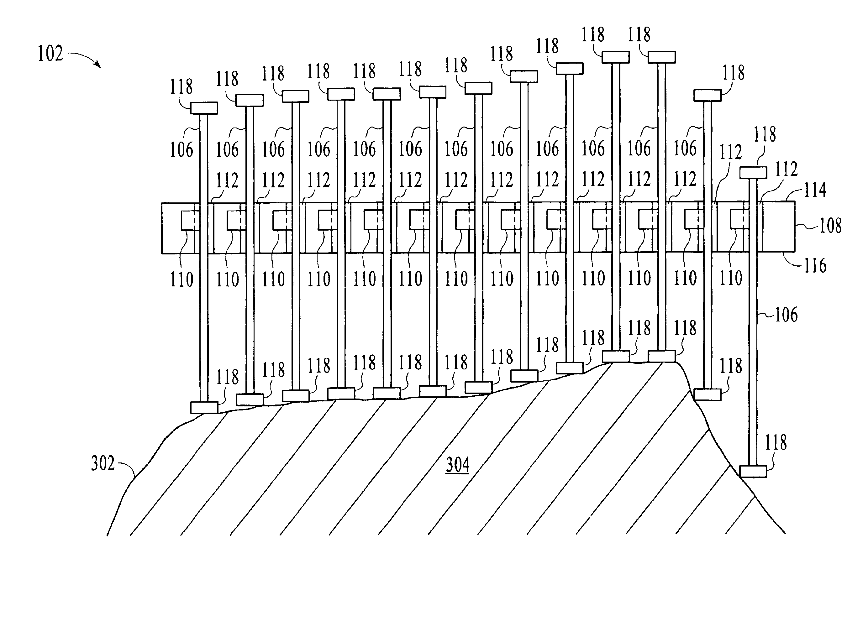
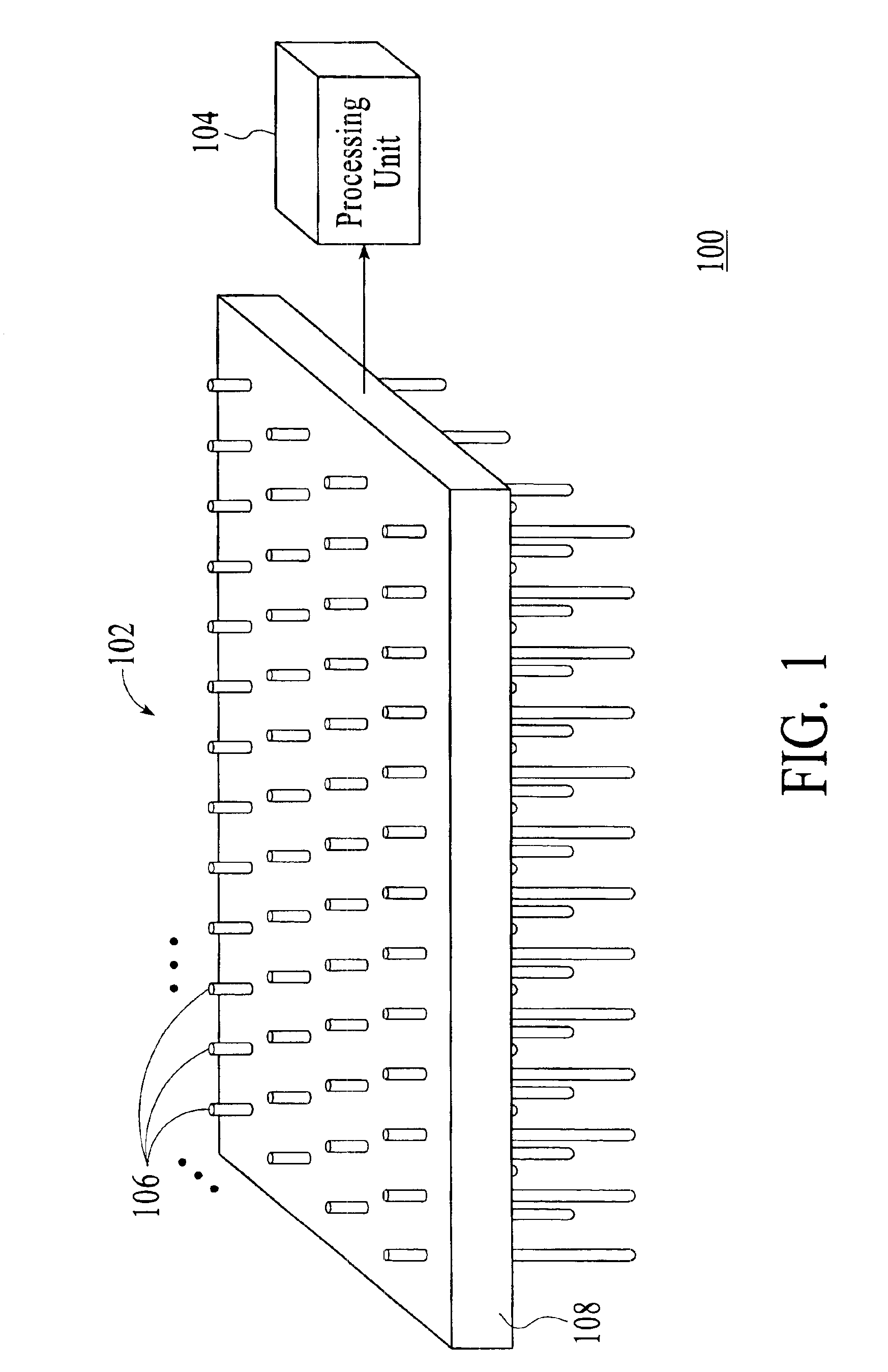
[0007]A system and method for measuring a three-dimensional object uses a number of elongate measuring members, such as pins, that can be displaced in a direction parallel to the central axes of the elongate measuring members in response to a surface of the object. The displaced distances of the measuring members are measurements of the object surface. These measurements can be used to create a virtual three-dimensional model of the measured object. The use of multiple measuring members allows the measurements to be made in parallel, which translates into a significantly shorter measuring process than conventional measuring techniques that acquire similar measurements one at a time.

Problems solved by technology

A concern with systems that use laser light for three-dimensional measurements is that timing of the laser light is limited by the switching frequency of the laser light and the delay measurements of the received laser light, which must be extremely precise especially when measuring small objects.
Another concern with such systems is that, if the object is highly reflective, such as a metallic object, or is transparent or translucent, the measuring systems may fail or provide unreliable measurements.
In addition, the mathematical triangulation problem is ill-defined for large areas of an object with the same color.
For instance, due to lack of contrast, it is practically impossible to measure small surface variations in a large white surface using triangulation based on photos.
Consequently, the process of measuring the surface points using such a measuring system requires a significant amount of time.

Method used


Image

  • System and method for measuring three-dimensional objects using displacements of elongate measuring members
  • System and method for measuring three-dimensional objects using displacements of elongate measuring members
  • System and method for measuring three-dimensional objects using displacements of elongate measuring members

Examples


Embodiment Construction

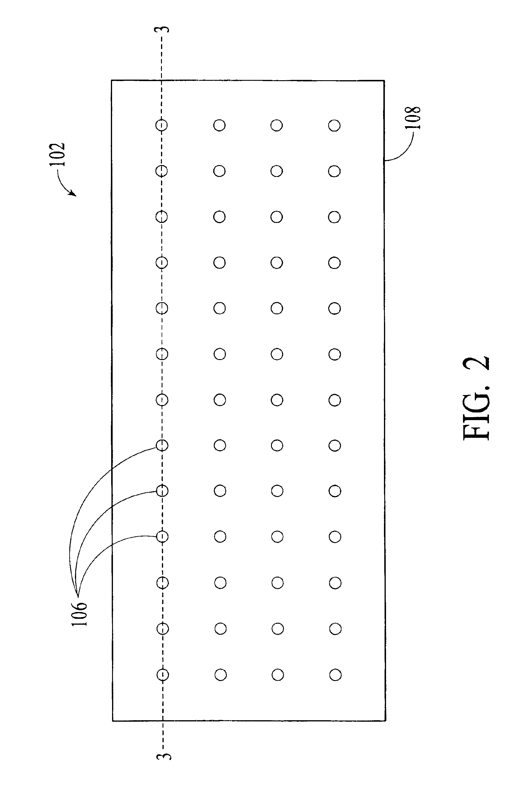
[0024]With reference to FIG. 1, a system 100 for measuring three-dimensional objects in accordance with an embodiment of the invention is shown. The system 100 operates to measure a surface of a three-dimensional object using a contact measuring technique. Consequently, the optical properties of the object surface do not impede or degrade the measurements made by the system 100. In contrast to conventional measuring systems, the contact measuring technique performed by the system 100 acquires multiple measuring points on the object surface to be measured in parallel. Thus, the system 100 can measure a three-dimensional object in a significantly shorter period than conventional systems, which typically employ contact measuring techniques that acquire similar measuring points one at a time.

[0025]As illustrated in FIG. 1, the system 100 includes a measuring device 102 and a processing unit 104. The measuring device 102 is designed to measure relative spatial positions of points on a su...


PUM


Abstract

A system and method for measuring a three-dimensional object uses a number of elongate measuring members that can be displaced with respect to a base in response to a surface of the object. The displaced distances of the elongate measuring members due to the surface of the object are then determined. The displaced distances are measurements of the object surface.

Description

FIELD OF THE INVENTION[0001]The invention relates generally to measuring systems, and more particularly to a system and method for measuring three-dimensional objects.BACKGROUND OF THE INVENTION[0002]A virtual or computer-generated three-dimensional model allows a user to easily manipulate and / or modify the model and its surrounding environment. Thus, virtual three-dimensional models of physical objects are widely used by professionals, such as animators, architects, designers, engineers and scientists. Virtual three-dimensional models are usually created by measuring physical objects using a contact or non-contact technique to extract spatial information from the physical objects. The spatial information is then processed to render the measured physical objects into virtual three-dimensional models.[0003]Some non-contact measuring techniques involve the use of laser light to measure relative positions of different surface points on a physical object. The relative distance measureme...

Claims


Application Information

Patent Timeline
Patent Type & Authority Patents(United States)
IPC IPC(8): G01B5/20G01B5/00G01B5/207
CPCG01B5/207G01B5/0002G01B11/24
Inventor SAID, AMIR
Owner HEWLETT PACKARD DEV CO LP
Learn More