Concrete hole cutting machine

a cutting machine and concrete technology, applied in cutting machines, agriculture tools and machines, agriculture, etc., can solve the problems of time-consuming, difficult, and expensive, and achieve the effect of convenient positioning

Inactive Publication Date: 2005-06-21
FAIRCLOTH TERRY
View PDF25 Cites 29 Cited by
  • Summary
  • Abstract
  • Description
  • Claims
  • Application Information

AI Technical Summary

Benefits of technology

[0007]Therefore, it is appreciated that the concrete hole cutting machine can be easily positioned such that the concrete cutting saw overlies and aligns with a target area to be cut. That is, the concrete saw can be first positioned with respect to a target area by simply positioning the front-end loader or tractor to where the concrete saw lies close to or in the vicinity of the target area. Next, the second frame structure can be shifted laterally back and forth with respect to both the first frame structure and the loader such that the concrete saw lies precisely over the target area. Then the concrete saw can be lowered into engagement with the target area for cutting a hole in the concrete slab.

Problems solved by technology

The problem lies in cutting the circular hole in the concrete slab.
This task is difficult, time consuming and in the end very expensive.
Simply bolting and securing the supported platform to the concrete slab is time consuming.
Concrete saws of the type discussed above are not portable.
This process is inconvenient and as noted above, a great deal of time and effort is expended in cutting each hole.

Method used


Image

  • Concrete hole cutting machine
  • Concrete hole cutting machine
  • Concrete hole cutting machine

Examples


Embodiment Construction

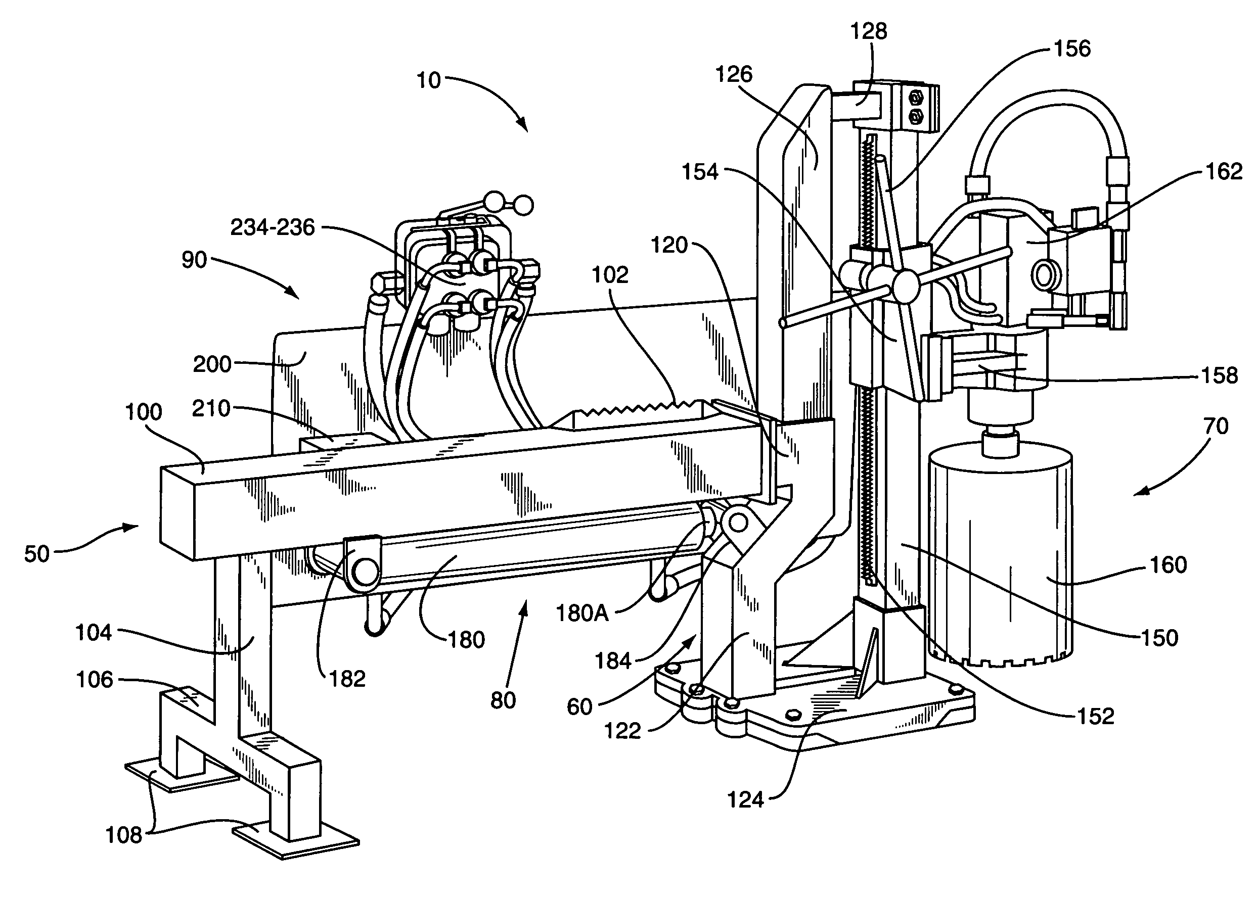
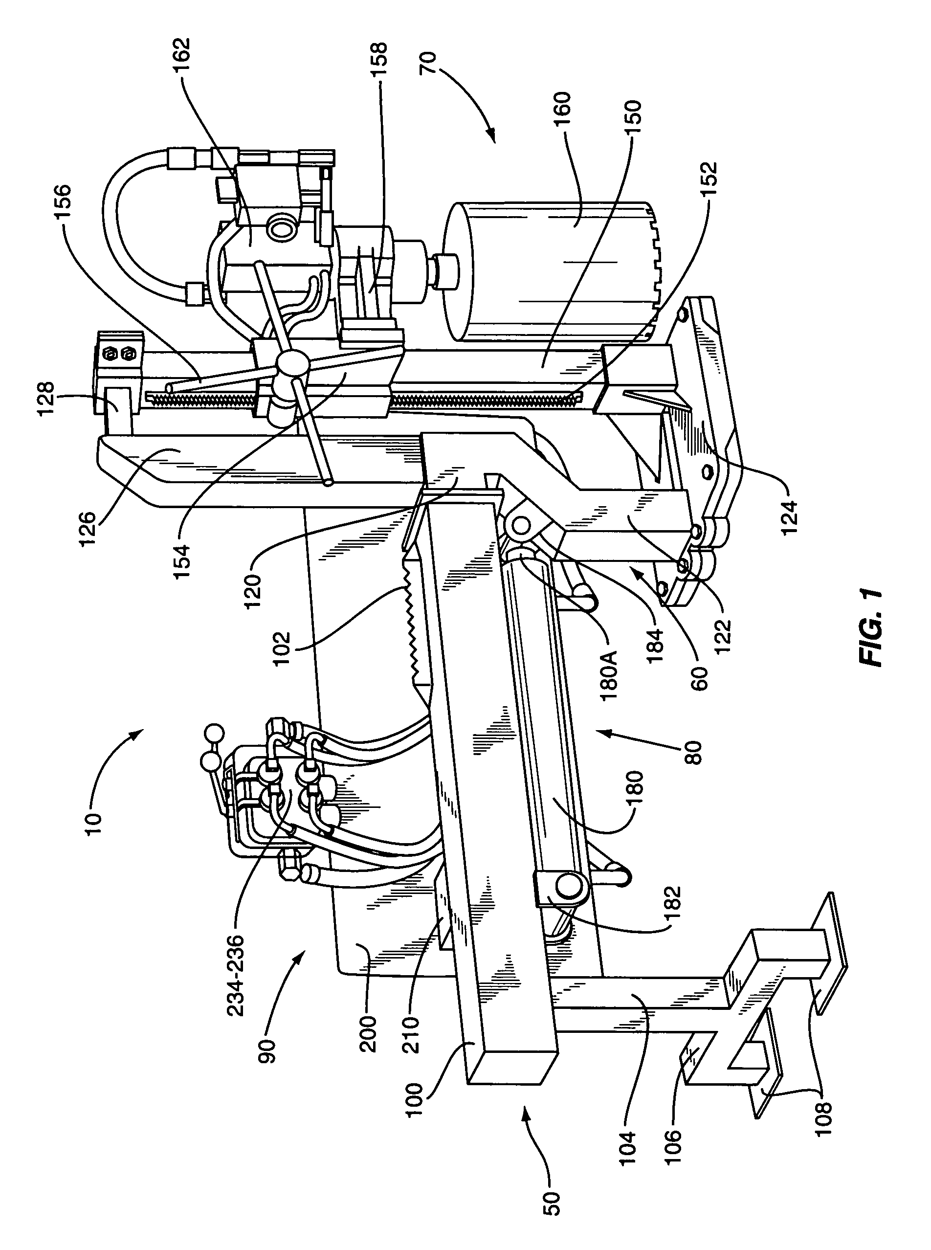
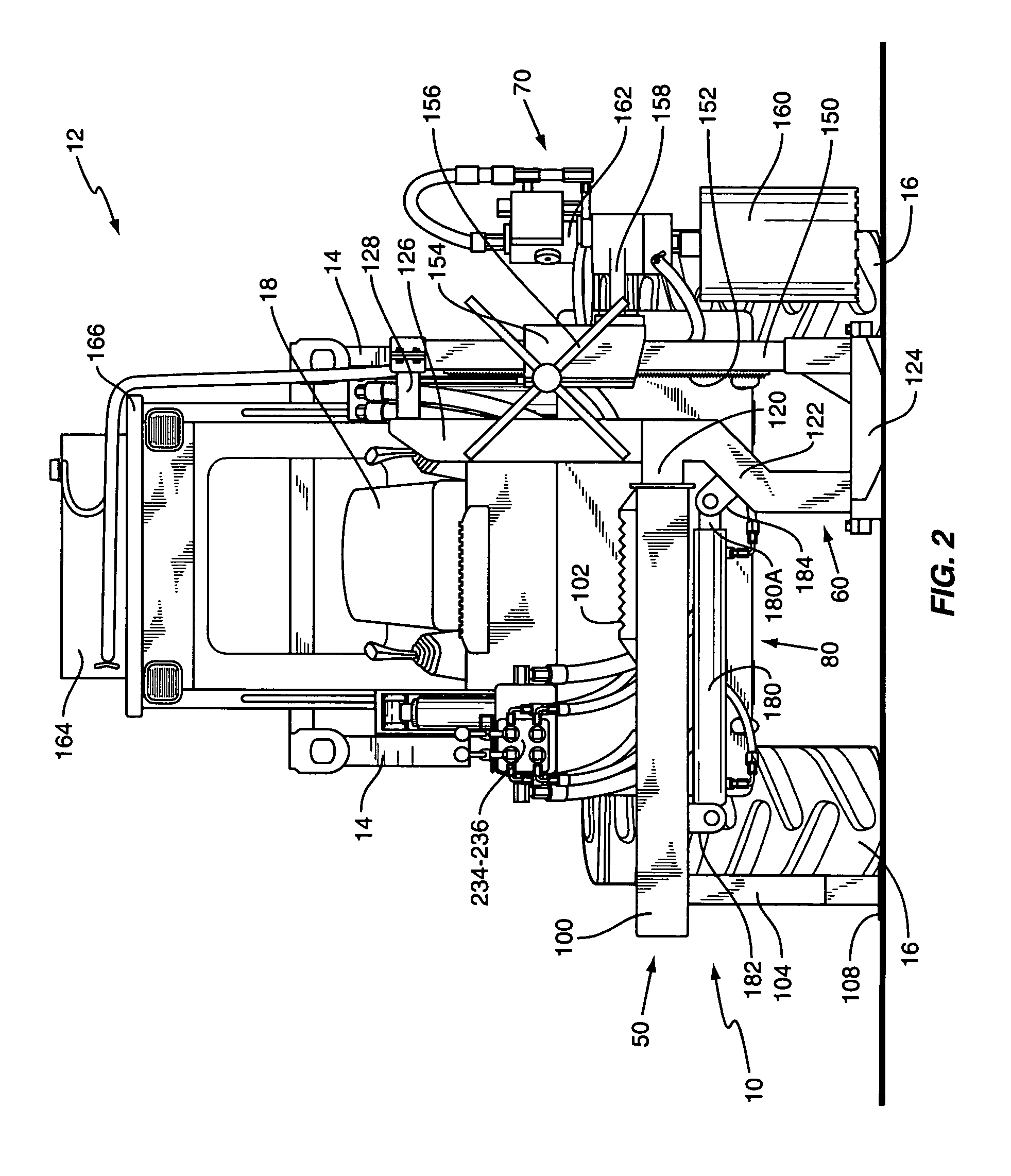
[0017]With further reference to the drawings, the concrete hole cutting machine of the present invention is shown therein and indicated generally by the numeral 10. As will be appreciated from subsequent portions of the disclosure, machine 10 is designed to cut holes in concrete slabs. Machine 10 is designed to be connected to a front-end loader indicated generally by the numeral 12. When connected to the front-end loader 12, machine 10 can be easily moved from one location to another location on a concrete slab and appropriately aligned with a target area such that a concrete saw, forming a part of the machine, may be lowered into engagement with the underlying concrete slab and a hole or cylindrical chunk of concrete cut from the slab.

[0018]Briefly reviewing front-end loader 12, it is noted that details of the front-end loader 12 are not dealt with herein because such is not per se material to the present invention and further front-end loaders are well known in the art and are ma...


PUM

PropertyMeasurementUnit
frame structureaaaaaaaaaa
areaaaaaaaaaaa
forceaaaaaaaaaa

Abstract

A machine for cutting holes in concrete slabs comprises a connector adapted to be secured to an adapter of a front-end loader. Secured to the connector is a first frame structure that includes an elongated tube and a support foot for engaging the surface of a concrete slab and supporting the first frame structure. Confined within the elongated tube of the first frame structure is a beam that is slidable back and forth therein. One end portion of the beam extends from the elongated tube. A second foot structure extends downwardly from the one end portion of the beam to where it may engage the surface of the concrete slab. Secured directly or indirectly to the elongated beam is a concrete hole cutting saw unit that includes a drum type concrete saw. Interconnected between the beam and the first frame structure is a hydraulic cylinder that is operative to move the elongated beam and saw cutting unit back and forth between a retracted and extended position. Accordingly, the concrete saw can be moved back and forth, laterally with respect to the front-end loader. By raising lift arms associated with the front-end loader, the concrete hole cutting machine can be moved from location to location. In use, the lift arms are lowered to where the two feet engage the upper surface of the concrete slab and the concrete saw is lowered into engagement with the concrete slab and by driving the concrete saw a circular hole is cut in the concrete slab.

Description

FIELD OF THE INVENTION[0001]The present invention relates to concrete saws and more particularly to a drum type concrete saw machine for cutting a hole in a concrete slab.BACKGROUND OF THE INVENTION[0002]Government safety regulations now require that posts be erected in some existing concrete slabs found in commercial and industrial sites. To erect a post in an existing concrete slab, requires that a circular hole be cut into and through the slab. Once a hole is cut into the slab a post is inserted into the hole and securely stationed therein by conventional means. The problem lies in cutting the circular hole in the concrete slab. This task is difficult, time consuming and in the end very expensive. Typically circular holes are cut in concrete slabs by a drum type concrete saw that is adjustably supported for up and down movement on a post that is in turn supported on a platform that rests on the concrete slab. However, it is important that the platform that supports the concrete s...

Claims


Application Information

Patent Timeline
Patent Type & Authority Patents(United States)
IPC IPC(8): B28D1/04
CPCB28D1/041
Inventor FAIRCLOTH, TERRY
Owner FAIRCLOTH TERRY
Why Eureka
Try Eureka