Cigar tip plug cutter

a cigar tip and cutter technology, applied in the field of cigar smoking accessories, can solve the problems of dragging the cigar tip, the inability to drill and cut with a penknife, and the difficulty of cutting

Inactive Publication Date: 2005-06-21
BELASCO JACOBS & TOWNSLEY
View PDF6 Cites 2 Cited by
  • Summary
  • Abstract
  • Description
  • Claims
  • Application Information

AI Technical Summary

Benefits of technology

[0025](9) In still another variant of the invention, a second detent is provided. The second detent is located on an outer surface of at least one of the support portions of the cigar plug ejector adjacent its lower end. The second detent serves to retain the cigar plug ejector in an upper position adjacent the platform cover, thereby preventing unwanted exposure of the upper end of the cylindrical blade.
[0029](13) In yet a further variant, the support platform further comprises a recess in its lower surface, the recess is sized, shaped and located to accept the base portion of the cigar plug ejector, thereby permitting the support platform to have a smooth lower surface when the cigar plug ejector is in an upper position.

Problems solved by technology

Drilling, however, can produce a ragged mouth-end for the cigar and, since one of the pleasures of cigar smoking is having a smooth cigar end inserted in the mouth, drilling and efforts to cut with a penknife have not been considered satisfactory.
While this type of cutter can be effective, at least initially, cutting becomes more difficult when the blade becomes duller, since the blade is simply forced axially against the tobacco packed inside the cigar wrapper.
It has also been found that occasionally cutters driven by rams can damage the end of the cigar against which they are placed because of the force exerted by both the blade and its supporting element.
While other more sophisticated cutters have been devised, some of them have been quite complicated in construction and operation and quite expensive to manufacture, with the result that they may price themselves out of range of the average cigar smoker.
In addition, recent airline regulations have severely restricted the transportation of many types of cutting devices aboard airplanes.

Method used


Image

  • Cigar tip plug cutter
  • Cigar tip plug cutter
  • Cigar tip plug cutter

Examples


Embodiment Construction

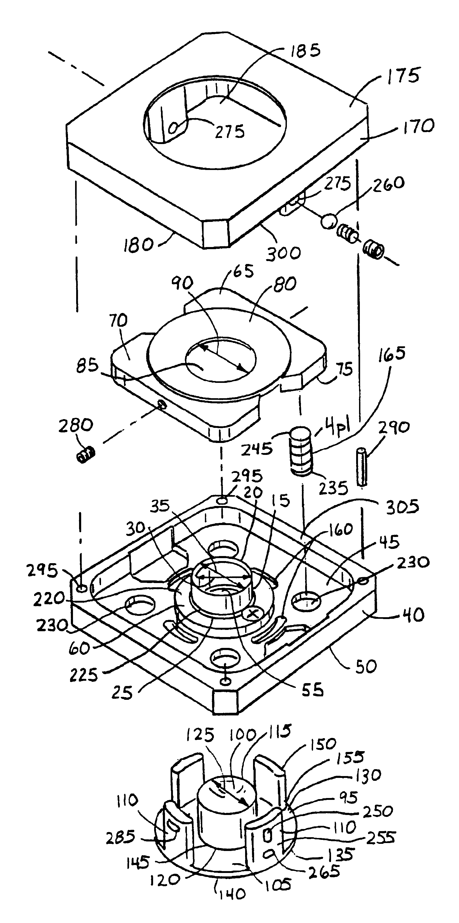
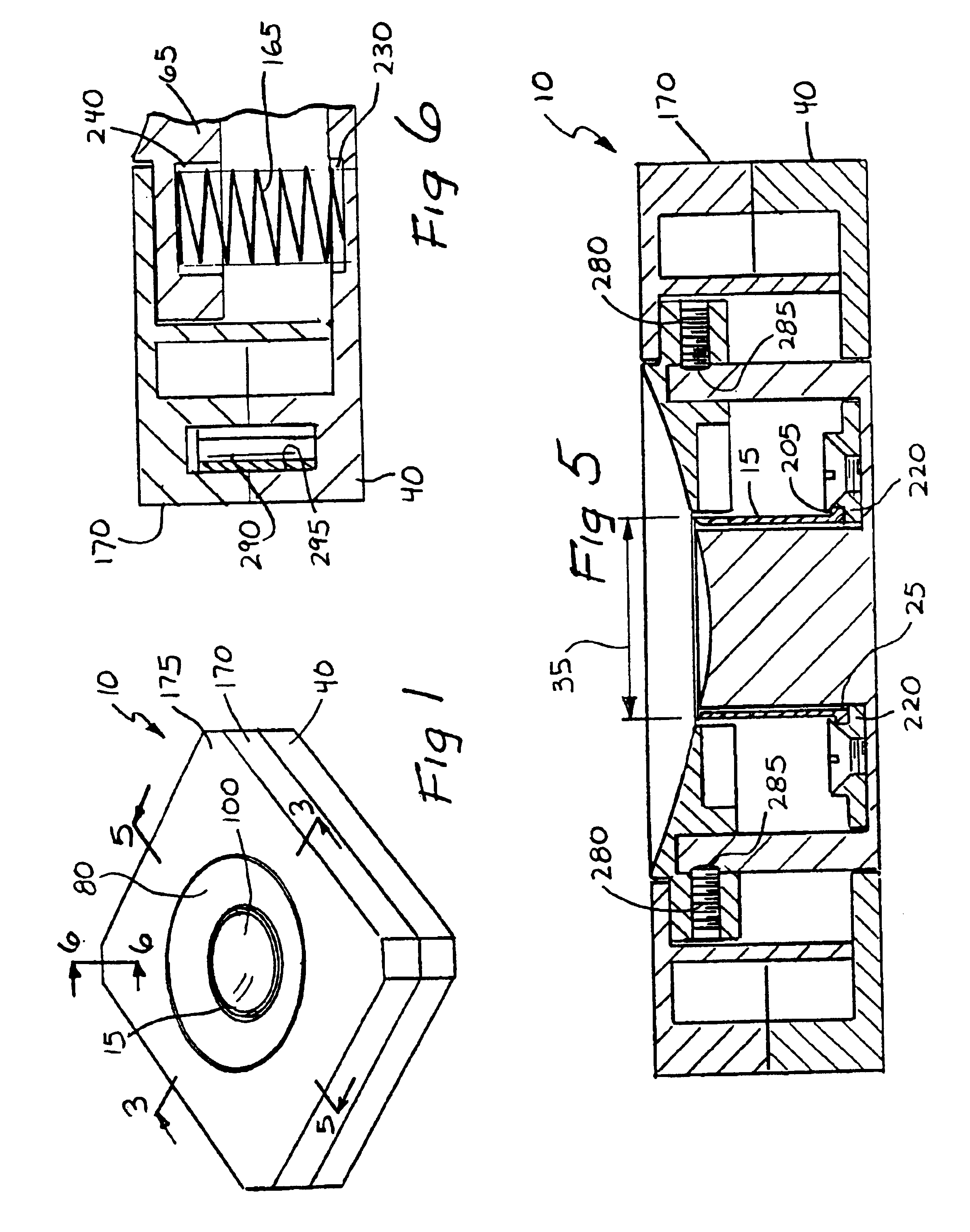
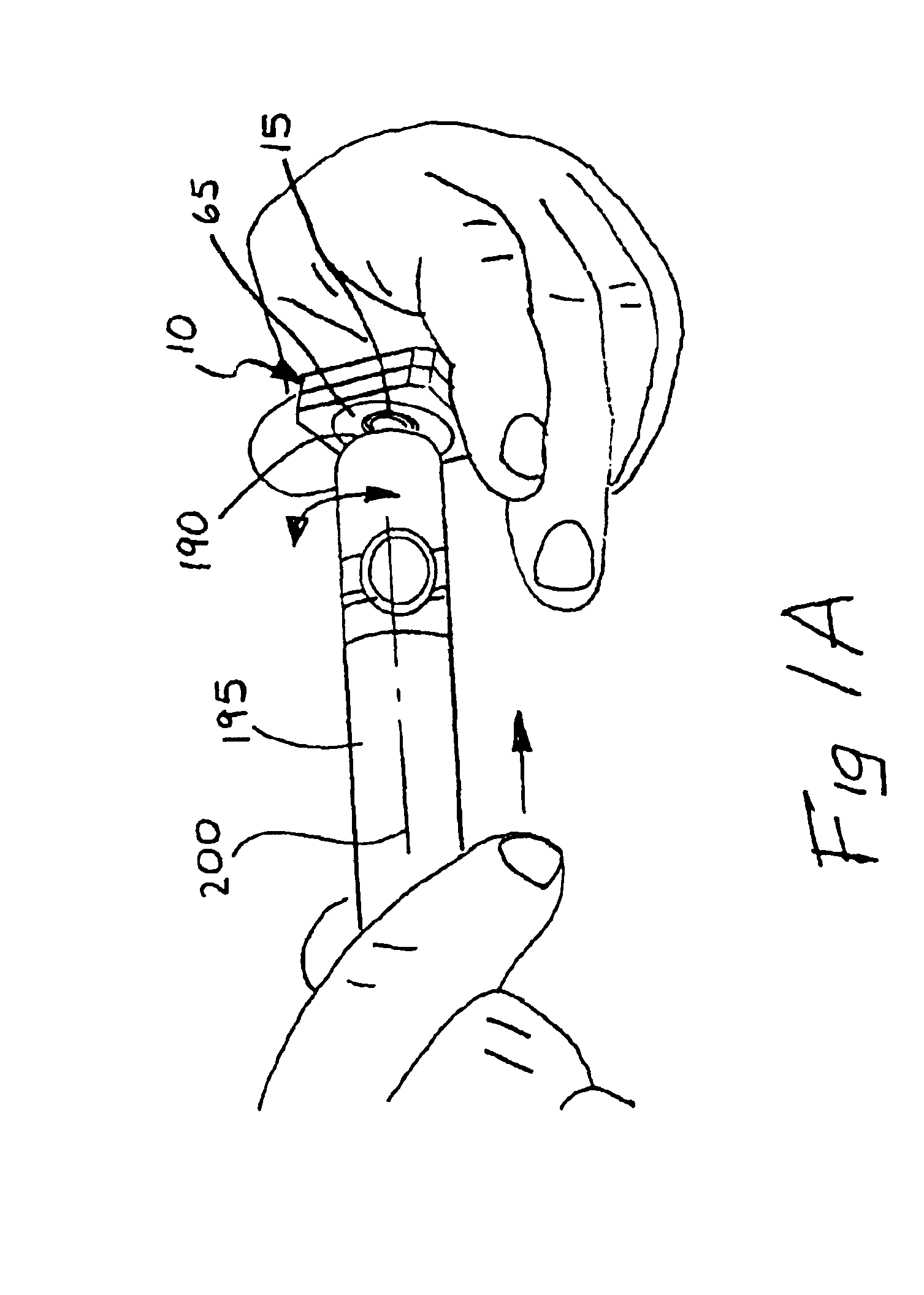
[0040](2) FIGS. 1-6 illustrate a cigar tip plug cutter 10 providing the desired features that may be constructed from the following components. As illustrated in FIGS. 2-5, a cylindrical cutting blade 15 is provided. The blade 15 has an upper end 20, a lower end 25, a first internal diameter 30 and a first external diameter 35. A support platform 40 is provided. The support platform 40 has an upper surface 45, a lower surface 50, a first central orifice 55 and means 60 for orthogonally mounting the cylindrical blade 15 above the first central orifice 55. A cigar tip receiving plate 65 is provided. The receiving plate 65 has an upper surface 70, a lower surface 75, a concave depression 80 in the upper surface 70 and a second central orifice 85 in the concave depression 80. The second central orifice 85 has a second diameter 90 greater than the first external diameter 35.

[0041]A cigar plug ejector 95 is provided. The ejector 95 has a rod portion 100, a base portion 105 and at least tw...


PUM


Abstract

A cigar tip plug cutter uses a cylindrical cutting blade to cut a round plug from the sealed end of a cigar. The cylindrical blade has a beveled upper edge tapering from the outer diameter to the inner diameter to better retain the cut plug. The blade is secured upright to a support platform and a cigar plug ejector rod projects upwardly through the blade. The ejector rod is secured to a base portion, as are at least two supports that attach to the underside of a cigar tip receiving plate. The plate has a central orifice to permit passage of the blade. The receiving plate is urged away from the support platform by compression springs that also cause the ejector rod to project into the blade. A platform cover fits slidably over the receiving plate and includes spring-loaded balls that maintain the receiving plate in upper and lower positions.

Description

FIELD OF INVENTION[0001]The invention pertains to cigar smoking accessories. More particularly, the invention relates to compact cigar tip cutting devices designed to provide an easy draw for cigar smokers.BACKGROUND OF THE INVENTION[0002]Ever since smoking of cigars came into vogue a number of centuries ago, it has been found desirable to cut the end of the cigar which is inserted in the smoker's mouth for a brief distance axially in order to enable the smoker initially to draw air through the wrapped tobacco in order to light the opposite end, and thereafter, to draw the desired smoke axially through the cigar into the smoker's mouth.[0003]In order to provide a suitable opening for this purpose, various instruments have been utilized to cut such an opening. These instruments have ranged from knives, including penknives, to sophisticated cutters that may cut off or even drill out a short axial opening. Drilling, however, can produce a ragged mouth-end for the cigar and, since one o...

Claims


Application Information

Patent Timeline
Patent Type & Authority Patents(United States)
IPC IPC(8): A24F13/24A24F13/00
CPCA24F13/24
Inventor KEMANJIAN, GARY K.
Owner BELASCO JACOBS & TOWNSLEY
Why Eureka
Try Eureka