Methods for treatment of a body cavity or lumen

a technology for treating the body cavity or the lumen, applied in the field of medical devices, can solve the problems of obviating the problems typically associated with the higher energy forms of treatment, affecting the treatment effect, so as to improve the distribution of ablative fluid, improve the effect of thermal load, and repeatable effect on the target organ

Active Publication Date: 2016-08-30
CHANNEL MEDSYST
View PDF60 Cites 7 Cited by
  • Summary
  • Abstract
  • Description
  • Claims
  • Application Information

AI Technical Summary

Benefits of technology

[0006]Generally, devices for delivering controlled treatment may comprise a source for a heated fluid and / or gas, e.g., hot water / steam, one or more pumps to deliver said hot water / steam, a catheter having one or more lumens defined therethrough and also having one or more ports to deliver or circulate the heated fluid and / or gas, e.g., hot water and / or vapor, to a controlled site in a controlled manner. The catheter may also have optional pressure sensing elements. The optional pressure sensing elements may allow the operator to monitor and / or control the pressure within the treatment zone and also prevent the pressure from becoming too high. The treatment site may be delineated by inflatable or expandable members which are pressurized or expanded to a target pressure to form a seal with the body cavity / lumen. The heated fluid and / or gas may then be delivered to the area contained by the inflatable / expandable members at a pressure that is less than that of the inflatable / expandable members thereby effectively containing the treatment area between these inflatable / expandable members. Optionally, a chilled or room temperature fluid such as water may then be used to rapidly terminate the treatment session.
[0007]The catheter having the inflatable / expandable members and optional pressure-sensing elements may be fitted within the lumen of an endoscope or other visualization device allowing the therapy to be delivered under direct visualization. In addition to direct visualization, this advance allows the scope to function as an insulator for the treatment catheter, thereby preventing unwanted exposure of body cavities / lumens to the elevated temperatures found in the heated fluid and / or gas coursing within the treatment catheter.
[0010]Additionally, the system may also incorporate features that may allow for efficacious therapy. For example, the system may utilize a sub-zero degrees Celsius temperature fluid lavage. This cold lavage may allow for much better control than charring and heating of the tissue and instead may provide a consistent depth of ablation in a manner that allows for rapid recovery and minimal post-operative pain (as opposed to heating methods). In addition, by using lavage of a fluid rather than cryogenic sprays (e.g., sprays which rely on the judgment of the user for determining time of spray application or spray location, etc.), the potential for over-ablation may be avoided. Also, the relatively colder cryogenic sprays have been found, in many cases, to result in damage to the endoscope while the higher temperatures possible with the system described herein (e.g., anywhere from −5 degrees Celsius to −80 degrees Celsius) is much less likely to damage the delivery equipment.
[0014]In yet another variation, the treatment fluid may function to expand the uterus for consistent ablation, function to distribute the cryoablative freezing more evenly throughout the uterus, and potentially function to prevent ice formation at the surface of the lumen or body cavity. In the uterus, for example, this layer of ice that may form on the surface of the endometrium is highly insulating and may prevent transmission of the cryoablative freeze zone to deeper surfaces requiring a longer treatment with potentially erratic effects. The apparatus may be used with, for example, lipophilic, hydrophilic or amphipathic solutions with the latter two being having the ability to remove any aqueous fluid from the surface of the target cavity or lumen which may interfere with conduction of the heat from the target tissues into the cryoablative fluid.

Problems solved by technology

When bodily tissues are exposed to even slightly elevated temperatures (e.g., 42 degrees C. or greater), focal damage may occur.
Exposure to these less elevated temperatures may allow for more controlled tissue damage and may obviate issues typically associated with the higher energy forms of treatment.

Method used


Image

  • Methods for treatment of a body cavity or lumen
  • Methods for treatment of a body cavity or lumen
  • Methods for treatment of a body cavity or lumen

Examples


Embodiment Construction

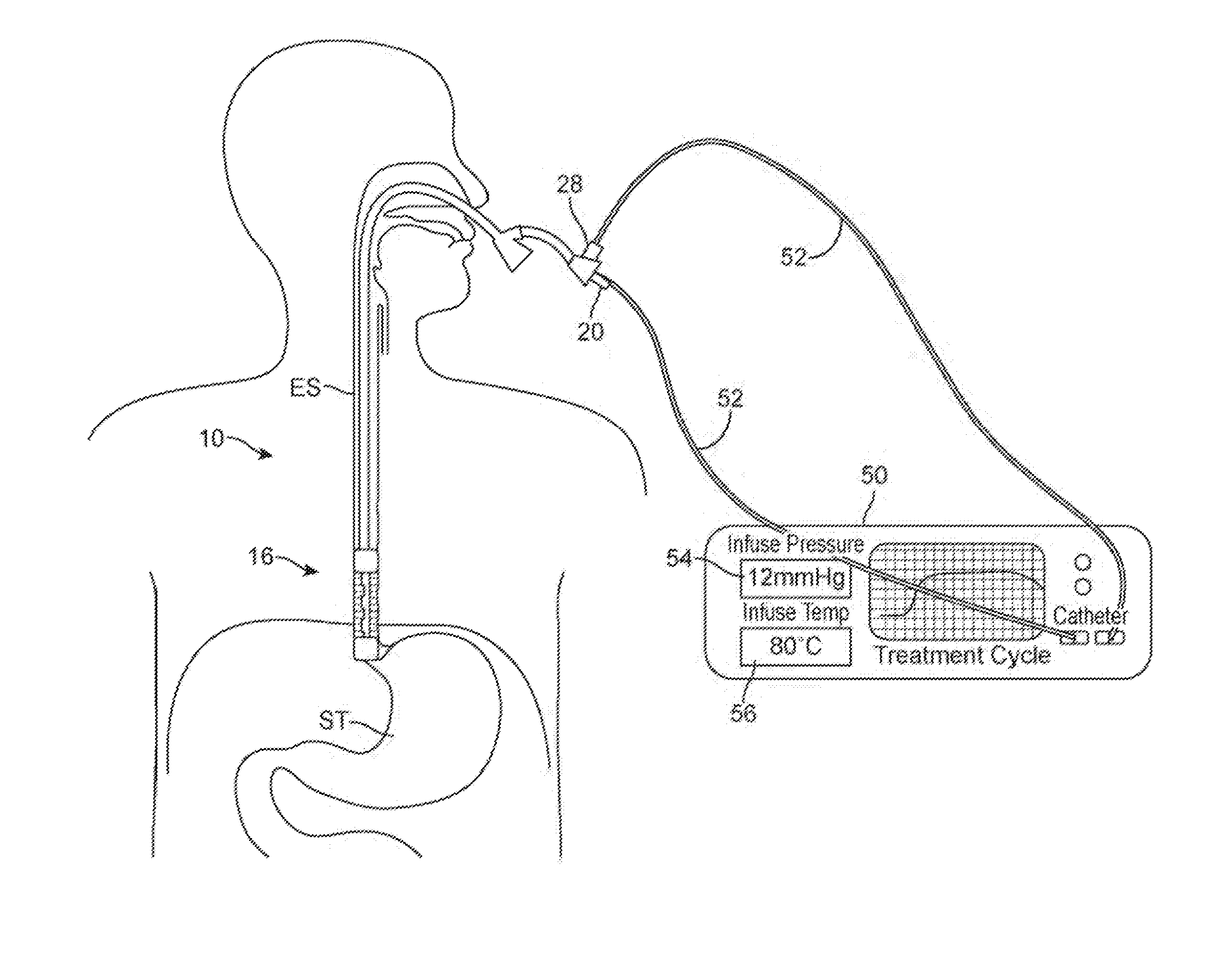
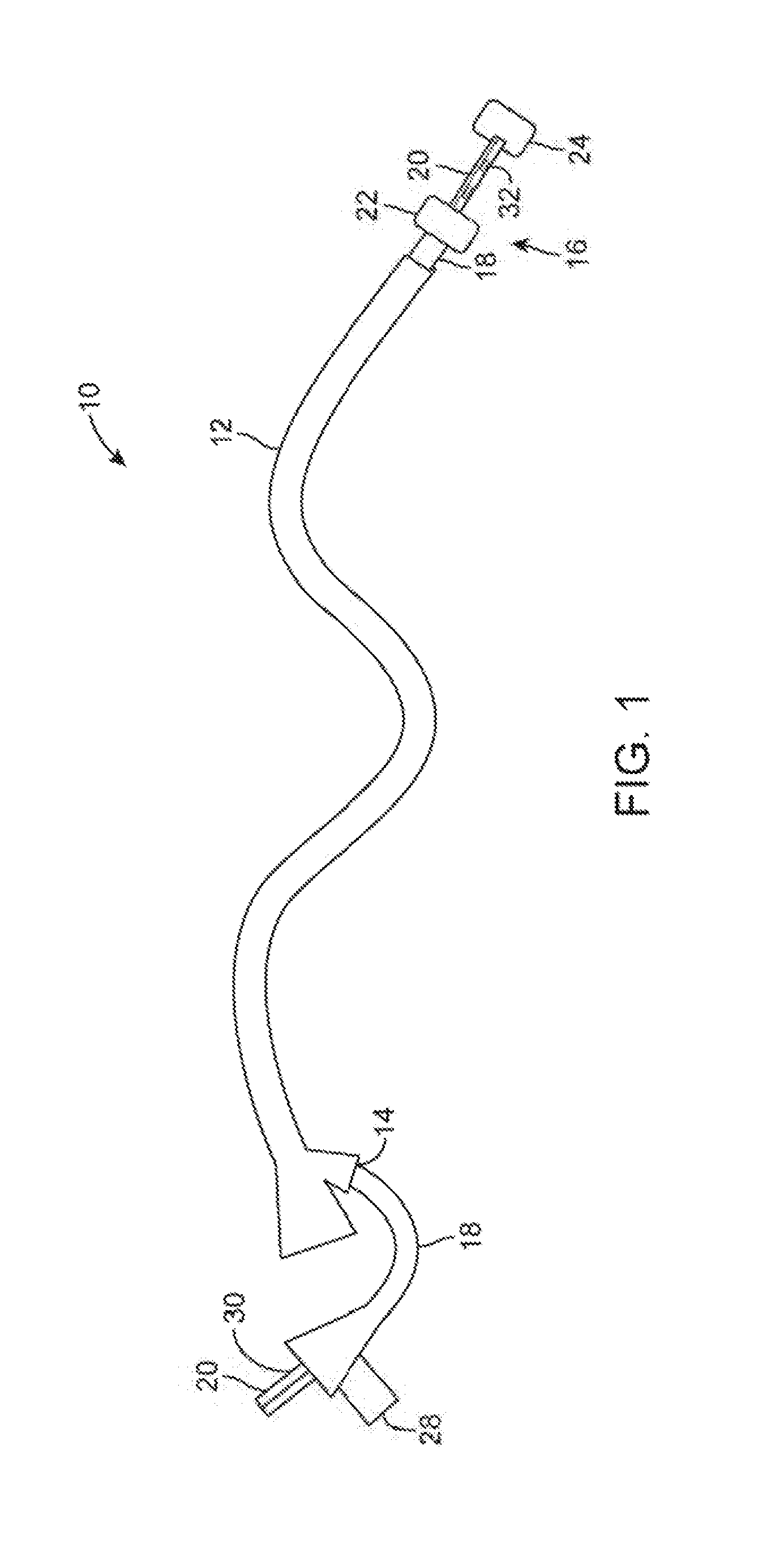
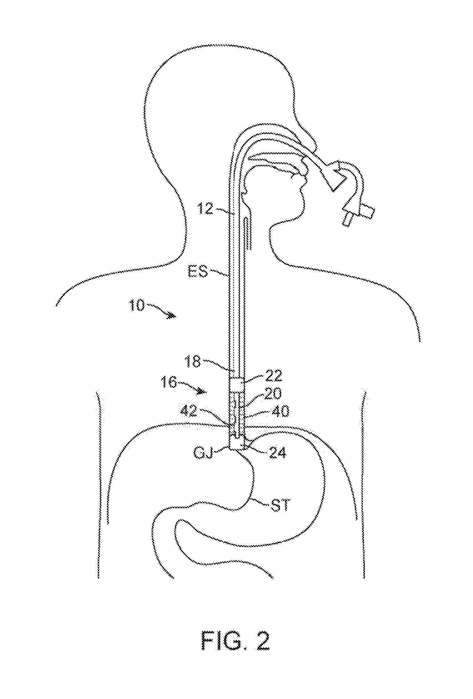
[0030]FIG. 1 shows a perspective view of one example of the treatment assembly 10 positioned within a working channel 14 of an endoscope 12 (e.g., orally or nasally insertable scope). In this example, the treatment device 16 itself may utilize a first catheter 18 having an inflatable or expandable balloon member 22 and a second catheter 20 that may slide freely with respect to the first catheter 18 and also having an inflatable balloon member 24 at its distal end. The first catheter 18 as well as second catheter 20 may have a fluid and / or gas tight seal 30 formed at the proximal end of the catheters. The inflatable and / or expandable members 22, 24 (shown in this example as inflated balloons) may be pressurized to effectively and safely occlude the lumen. The balloons may be filled with chilled or room temperature fluid to prevent possible damage caused by balloon rupture or seepage around the balloon. Pressure within the inflatable or expandable balloon members may also be monitored...


PUM


Abstract

Methods and apparatus for the treatment of a body cavity or lumen are described where a heated fluid and / or gas may be introduced through a catheter and into treatment area within the body contained between one or more inflatable / expandable members. The catheter may also have optional pressure sensing elements which may allow for control of the pressure within the treatment zone and also prevent the pressure from exceeding a pressure of the inflatable / expandable members to thereby contain the treatment area between these inflatable / expandable members. Optionally, a chilled or room temperature fluid such as water may then be used to rapidly terminate the treatment session.

Description

CROSS-REFERENCE TO RELATED APPLICATIONS[0001]This application is a continuation of PCT International Patent Application No. PCT / US2010 / 036947 filed Jun. 1, 2010 which claims priority to U.S. Prov. 61 / 217,537 filed Jun. 1, 2009; 61 / 277,770 filed Sep. 30, 2009; and 61 / 337,648 filed Feb. 11, 2010, each of which is incorporated herein by reference in its entirety.FIELD OF THE INVENTION[0002]The present invention relates to medical devices. In particular, the present invention relates to methods and apparatus for therapeutic devices capable of exposing areas of the body to elevated or decreased temperatures, in a highly controlled manner.BACKGROUND OF THE INVENTION[0003]In the last few decades, therapeutic intervention within a body cavity or lumen has developed rapidly with respect to delivery of energy via radiofrequency ablation. While successful in several arenas, radiofrequency ablation has several major downsides, including incomplete ablation, frequent lack of visualization during...

Claims


Application Information

Patent Timeline
Patent Type & Authority Patents(United States)
IPC IPC(8): A61M25/10A61B18/04A61B18/00A61M25/00A61M25/01A61F2/958
CPCA61B18/04A61M25/10A61B2018/00023A61B2018/046A61M2025/0002A61M2025/0003A61M2025/0175A61M2025/1015A61M2025/1052A61M2210/105A61M2210/1433A61B2090/064A61B18/02
Inventor BURNETT, DANIEL ROGERS
Owner CHANNEL MEDSYST
Why Eureka
Try Eureka