Hand winch having a removable sway handle

Inactive Publication Date: 2005-06-21
HSIEN CHING FONG
View PDF5 Cites 22 Cited by
  • Summary
  • Abstract
  • Description
  • Claims
  • Application Information

AI Technical Summary

Benefits of technology

[0003]The present invention has a main object to provide a hand winch having a removable sway handle which is readily assemb

Problems solved by technology

However, this type of the hand winch 10 has a large volume, especially its long sw

Method used


Image

  • Hand winch having a removable sway handle
  • Hand winch having a removable sway handle
  • Hand winch having a removable sway handle

Examples


Embodiment Construction

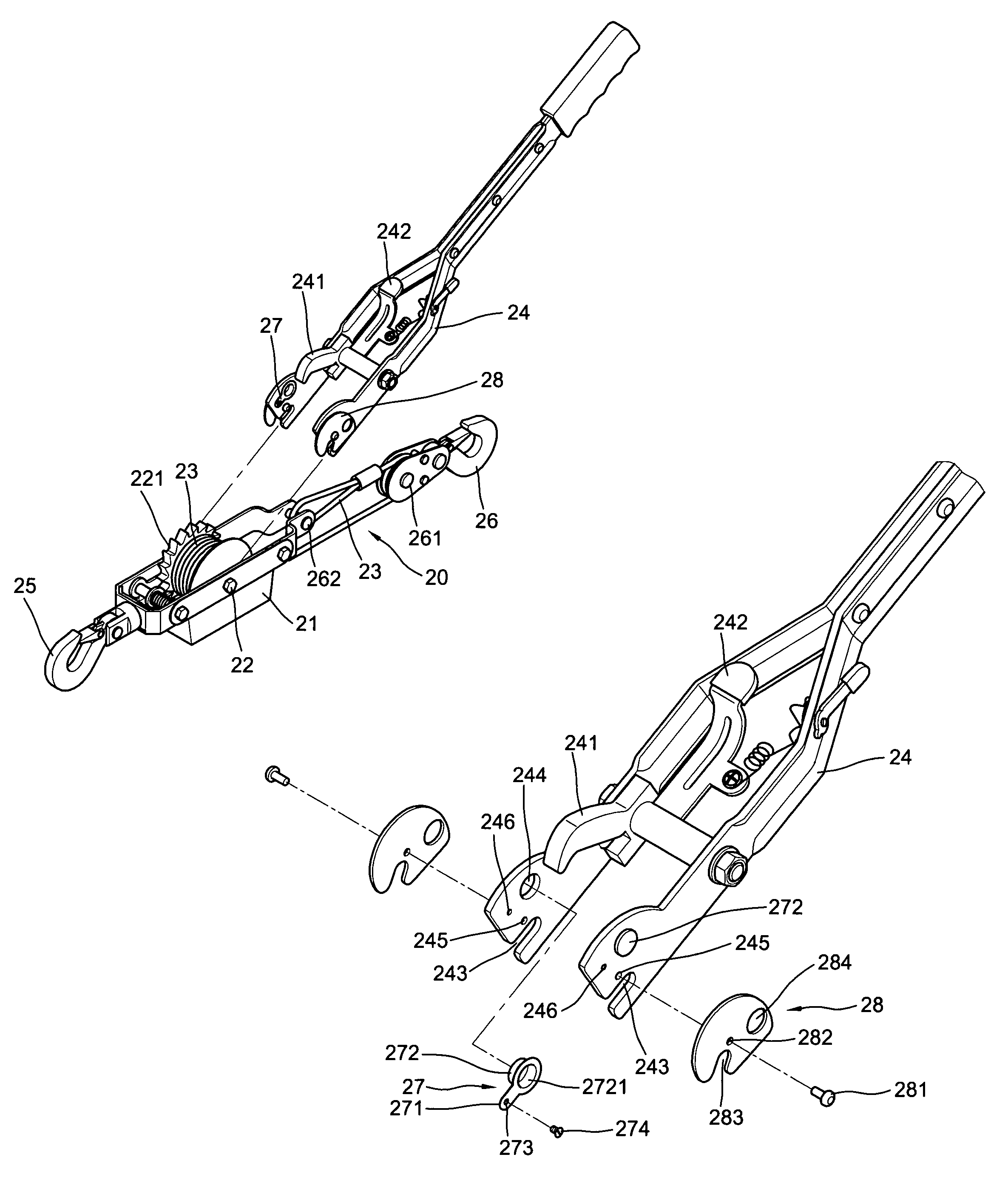
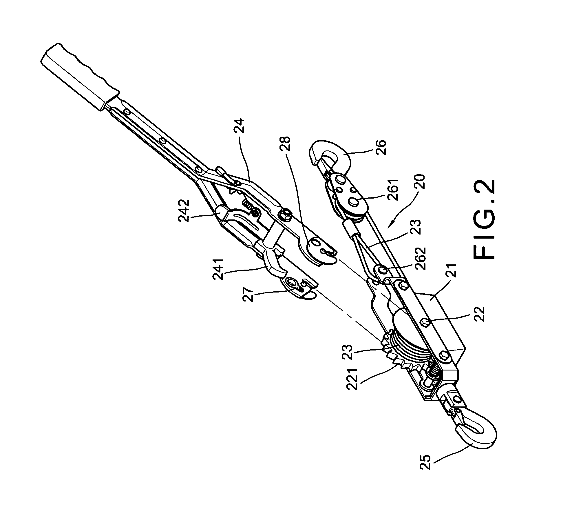
[0015]With reference to the drawings and initiated from FIGS. 2, 3 and 4, the hand winch 20 of the present invention comprises a main body 21, a main axis 22 having a winding drum thereon for winding a cable 23 and plurality of ratchet teeth 221 of single direction on a lateral side, a tongs shaped sway handle 24 removable pivoted to the main axis 22. The sway handle has a check pawl 241 pivoted to a transverse rod engageable within the teeth 221 and operated by a lever 242 which is positioned under the check pawl 241 and connected to an inner side of a prong of the sway handle 24 by a spring, a U-shaped concave 243 in the front end of each of the prongs of the sway handle 24, a small hole 245 above the concaves 243, a circular through hole 244 and a screw hole 246 spacedly formed above the small holes 245. A pair elastic members 27 each having an elastic plate 271, a cap 272 including an opening 2721 in inner side respectively engaged within the circular through holes 244 from the ...


PUM


Abstract

A hand winch having a removable sway handle includes a main body having a winding drum and a plurality of ratchet teeth thereon for winding a cable, a subordinate hook secured to one end of the main body, a main hook suspended from the distal portion of the cable which is fastened to the other end of the main body, a sway handle a tongs shaped front portion composed of a pair of symmetrical prongs each of which has a concave respectively engaged with the main axis and rotatably fixed by a pair of movable plates in cooperation with a pair of elastic members each of which has a cap protruded to outside of the prongs and engaged with a circular through hole of the movable plates, a check pawl engaged within the ratchet teeth and rotatably operated by a lever in the tongs shaped front portion. Thereby, press inward of the caps to set the movable plate free to rotate in order to permit the sway handle readily removed from the main body.

Description

BACKGROUND OF THE INVENTION[0001]The present invention relates to hand winch and / or capstan and more particularly to a hand winch having a removable sway handle.[0002]A hand winch is useful to drag a car, a boat, a heavy machine and / or to bind the timbers. FIG. 1 shows a prior art hand winch 10 which comprises a winding drum 11 for winding the cable 12, a plurality of single direction ratchet teeth 13 on a lateral side, a sway handle 14 having a check pawl 141 which checks the ratchet teeth upon the operation of the sway handle 14, a main hook 15 and a subordinate hook 16 respectively connected with two ends of the cable 12. In operation, the main hook 15 hooks a rope which is supposedly fastened on a post and the subordinate hook 16 hooks another rope which is supposedly fastened on a heavy machine. Then press the check pawl 141 downward to engage with one of the ratchet teeth 13 and sways the sway handle 14 to and fro so as to gradually move the machine step by step. However, this...

Claims


Application Information

Patent Timeline
IPC IPC(8): B66D3/00B66D3/04
CPCB66D3/04Y10T16/469
Inventor HSIEN, CHING-FONG
Owner HSIEN CHING FONG
Why Eureka
Try Eureka