
Optical disk, optical reproduction device, and optical recording device

a technology which is applied in the field of optical recording device and optical disk, can solve the problems of inability to detect the normal clock signal from the clock mark, the likelihood of even a small flaw negatively affecting the clock mark, and the disk flaw is susceptible to disk flaws, etc., and achieves high reliability in recording and reproduction.

Inactive Publication Date: 2005-06-21
SHARP KK
View PDF17 Cites 5 Cited by
  • Summary
  • Abstract
  • Description
  • Claims
  • Application Information

AI Technical Summary

Benefits of technology

[0037]The present invention, in view of the above problems, has an object to offer an optical disk, an optical reproduction device, and an optical recording device that are capable of performing highly reliable recording and reproduction even if a clock mark is defective due to a flaw.
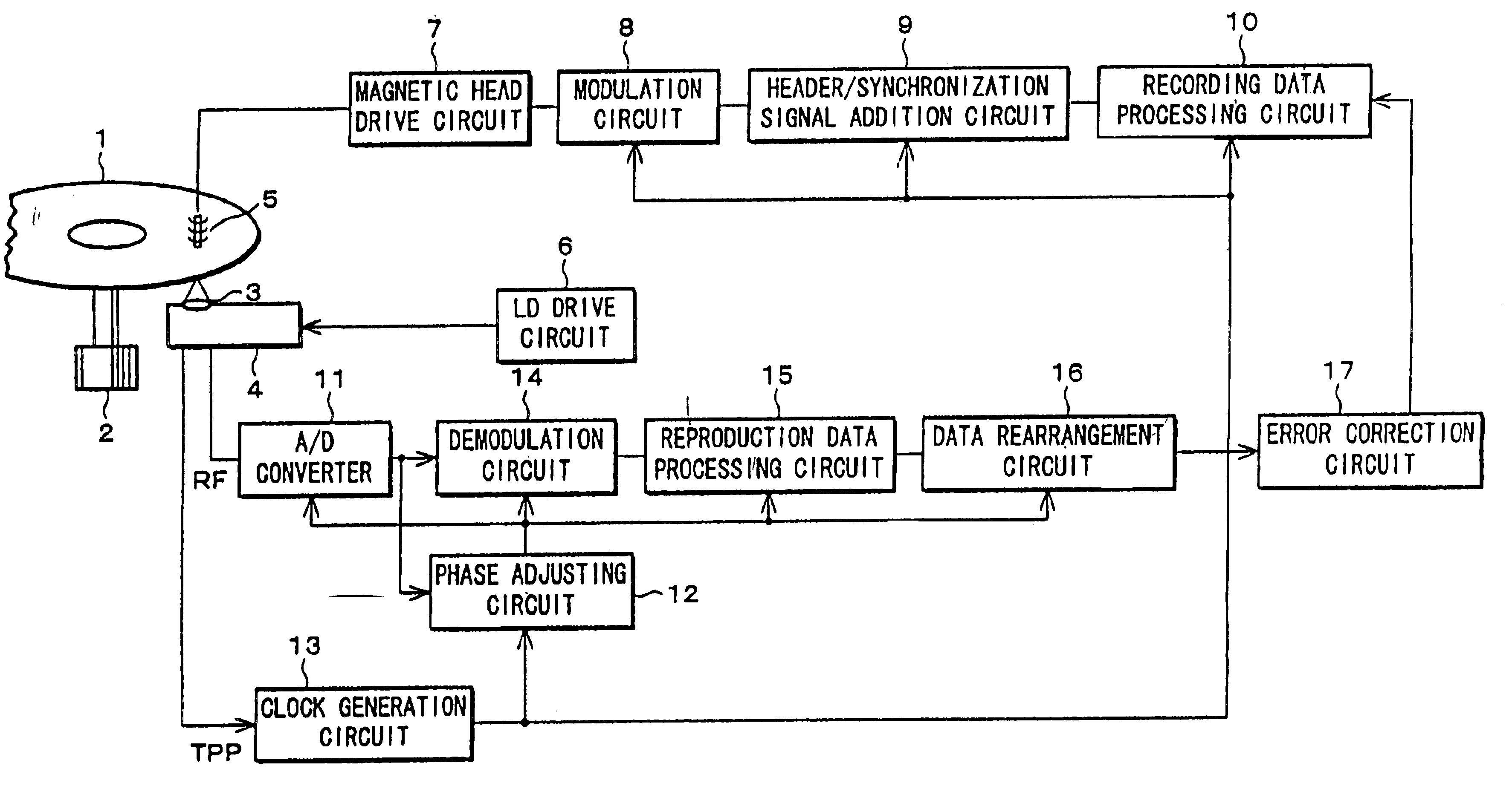
[0045]In other words, the displacement of the data caused by a defective clock mark can be corrected according to the synchronization pattern recorded in the synchronization field in the data segment for subsequent data so as to restore the data in subsequent data segments to standard position. Therefore, the error caused by the displacement is confined to a minimum amount of data, allowing large data to be reproduced correctly.
[0050]A defect in the clock mark obstructs the generation of a correct clock signal by the clock generation circuit and causes displacement of the data when recorded; however, with the arrangement above, the displacement can be corrected according to the synchronization pattern detected by the data rearrangement circuit. Therefore, the data in the data segments subsequent to the data segment for the displaced data can be reproduced correctly. This realizes highly reliable recording and reproduction with few data errors.
[0055]With the arrangement above, a synchronization pattern is added to data recorded in at least some of the data segments; therefore, even if a defective clock mark causes the data to be displaced when recorded, the data in the data segments subsequent to the data segment for the data displaced can be recorded correctly by correcting the displacement according to a synchronization pattern in a data segment subsequent to the data segment for the displaced data. Therefore, the error caused by the displacement is confined to a minimum amount of data, allowing large data to be reproduced correctly. This realizes highly reliable recording and reproduction with few data errors.

Problems solved by technology

The method, however, is susceptible to disk flaws, because the use of clock marks enables the detection of clock signals with shorter mark lengths, but inevitably increases, with decreasing mark lengths, the likelihood of the presence of even a small flaw negatively affecting the clock mark.
A normal clock signal cannot be detected from a clock mark, if the clock mark is defective due to a flaw.
However, the defect in the clock mark located at the head of the data segment DS3 lowers the frequency, that is, extends the cycle, of the bit clocks in the data segment DS3 and thereby reduces the number of the bit clocks to 507 or even further.
When this is the case, the number of bit clocks in the data segment DS3 in a reproduction operation differs from that in a recording operation, obstructing normal reproduction.
However, if the number of clocks corresponding to the data segment DS3 differs between recording and reproduction operations, the data in the data segment DS4 and its subsequent data segments is not divided correctly into 1-byte pieces of data.
In short, if, the conventional optical disk and optical disk device fails to correctly detect the clock signal, the data-is displaced and cannot be recorded and reproduced.

Method used


Image

  • Optical disk, optical reproduction device, and optical recording device
  • Optical disk, optical reproduction device, and optical recording device
  • Optical disk, optical reproduction device, and optical recording device

Examples


Embodiment Construction

[0067]Referring to the drawings, the following description will discuss an embodiment in accordance with the present invention.

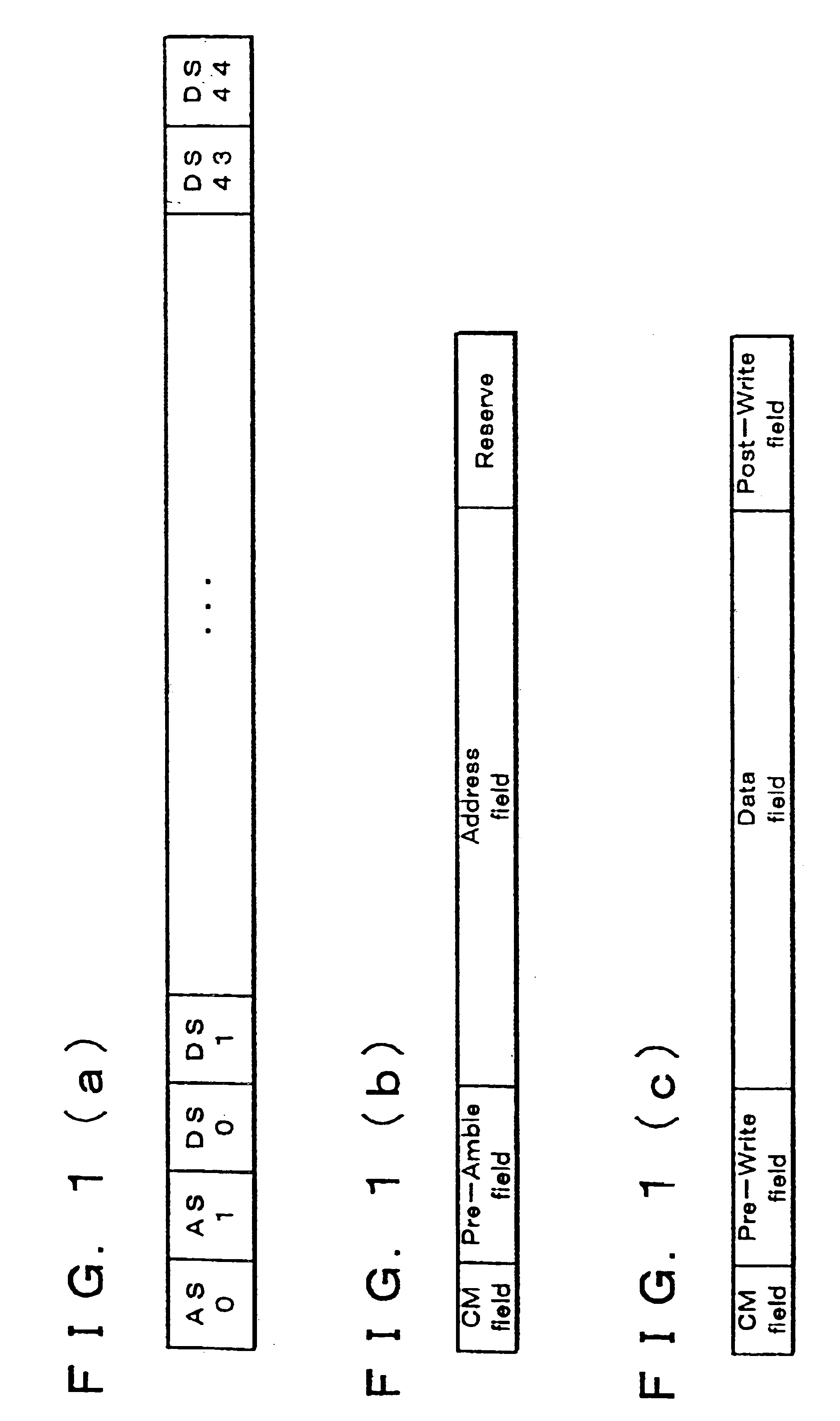
[0068]FIG. 1(a) to FIG. 1(c) are explanatory drawings showing a format of an optical disk in accordance with the present invention. FIG. 1(a) shows an arrangement of a sector. Each sector is constituted by two address segments AS0 and AS1 and 45 data segments DS0 to DS44. The number of the address segments and data segments shown here may be changed according to use.

[0069]FIG. 1(b) shows an arrangement of an address segment. The address segments AS0 and AS1 each include a clock mark field (CM field), an address field, a preamble field, and other fields. In each field, a predetermined signal is recorded in advance in the form of a variation in the shape of a pit or a groove.

[0070]The clock mark field records in advance a clock mark from which a clock signal is generated as mentioned in the foregoing. The address field records the address of the sector. The ot...


PUM

PropertyMeasurementUnit
displacementaaaaaaaaaa
light reflectanceaaaaaaaaaa
densityaaaaaaaaaa

Abstract

An optical disk has a recording track constituted by sectors arranged in a concentric or spiral form. Each sector is divided into segments, and each segment includes a data field where data is recorded and a clock mark field having a different light reflectance from that of the data field. The data field in the sector has synchronization patterns S. Hence, a highly reliable optical disk, optical reproduction device, and optical recording device can be offered that are capable of performing recording and reproduction even if a clock mark is defective due to a flaw.

Description

FIELD OF THE INVENTION[0001]The present invention relates to optical disks and optical disk devices, and in particular, to optical disks, optical reproduction devices, and optical recording devices that are capable of preforming reliable recording and reproduction.BACKGROUND OF THE INVENTION[0002]We have in recent years witnessed digital information being offered in dramatically increasing quantities, as various contents including video and audio have become available in digital format. In response to this trend, development is under way to design optical disk devices suitable to increasing capacity and density. Meanwhile, considering that the quality of reproduction signals deteriorates with increase in density, various solutions are suggested to improve the quality of reproduction signals.[0003]Reproduction signals carry, in addition to image and other main information, servo information and other various kinds of control and management information. Among those kinds of informatio...

Claims


Application Information

Patent Timeline
Patent Type & Authority Patents(United States)
IPC IPC(8): G11B27/19G11B27/30G11B27/24G11B7/0045G11B7/005G11B7/007G11B7/00G11B11/105G11B11/00G11B7/0037G11B20/10G11B20/12
CPCG11B7/0045G11B7/005G11B7/00745G11B27/19G11B27/24G11B27/3027G11B7/0037G11B11/10508G11B2220/2562G11B11/10595G11B2220/2525G11B11/10515G11B20/10222G11B2220/2537G11B2220/216
Inventor AKIYAMA, JUNMAEDA, SHIGEMI
Owner SHARP KK
Learn More