
Optical recording medium and method of manufacturing thereof, and recording and reproducing method

Inactive Publication Date: 2006-03-30
RICOH KK
View PDF6 Cites 2 Cited by
  • Summary
  • Abstract
  • Description
  • Claims
  • Application Information

AI Technical Summary

Benefits of technology

[0012] An object of the present invention is to provide an optical recording medium at which a sufficient focusing characteristic can be obtained even at recording speeds at which the recording linear velocity exceeds 4× speed (recording linear velocity=14 m / sec) at the same capacity as a DVD-ROM, and in-plane fluctuations in the degree of modulation can be suppressed, and highly reliable recording is possible, and a method of manufacturing the optical recording medium, and a recording and reproducing method.
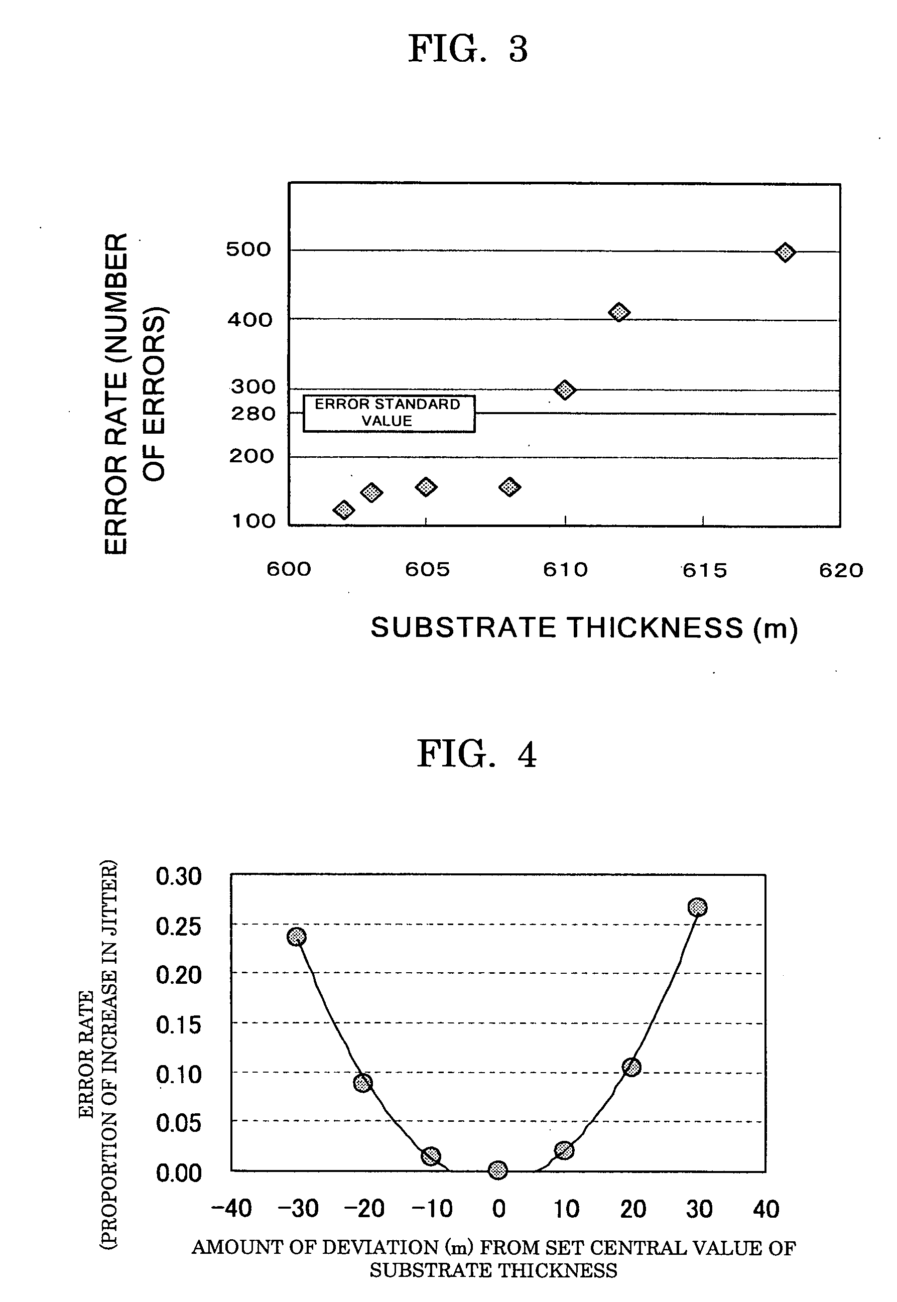
[0015]<1> an optical recording medium having a substrate, and at least a recording layer and a reflective layer on the substrate, wherein the optical recording medium is formed such that the substrate has a set central value of a thickness, and when there is a substrate thickness within a given range from the set central value, an axial direction acceleration of the optical recording medium has a maximum allowable value, and as an amount of deviation from the set central value exceeds the given range, a maximum allowable value of the axial direction acceleration at the optical recording medium becomes smaller.
[0025]<11> a method of manufacturing an optical recording medium having at least a recording layer and a reflective layer on a substrate, wherein the optical recording medium is manufactured by controlling such that, when a substrate thickness is within a given range from a set central value, an axial direction acceleration of the optical recording medium has a maximum allowable value, and as an amount of deviation from the set central value of the substrate thickness exceeds the given range and becomes larger, a maximum allowable value of the axial direction acceleration becomes smaller.

Problems solved by technology

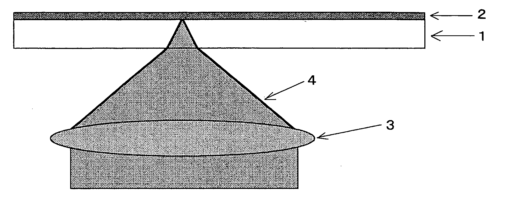
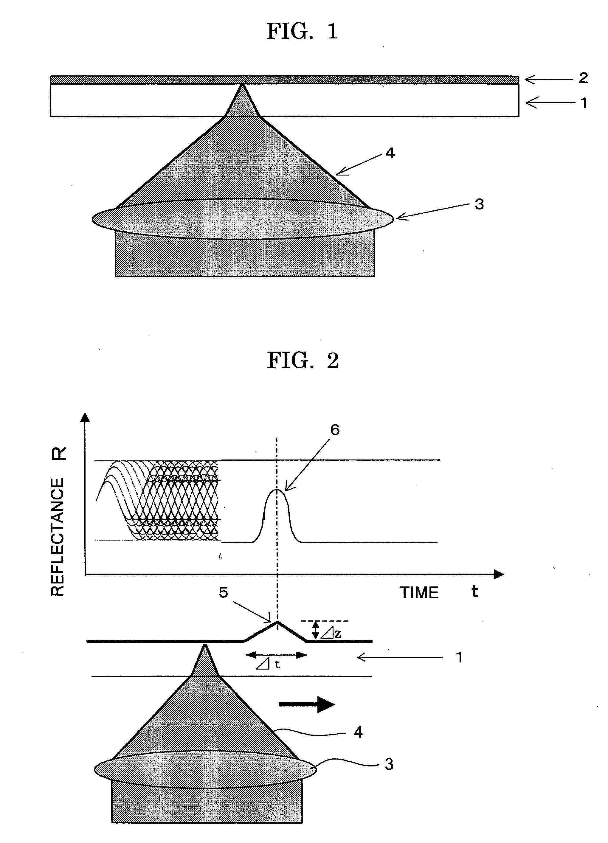
In order to overcome the above-described problems, the present inventors carried out diligent studies, and as a result, in a case in which recording or reproducing a signal is carried out via a substrate, when warping (and convex portions in particular) due to static or dynamic deformation of the substrate arises, aberration of the collected laser beam arises due to this warping, and this aberration causes problems such as a deterioration in the reproduction signal, a decrease in the effective recording power, so-called “recording omissions”, and the like.
In particular, because the effects of warping occurring locally at the substrate increase in proportion to the square of the speed, these problems become more marked and affect the recording characteristic as recording and reproducing speeds become higher speeds.

Method used


Image

  • Optical recording medium and method of manufacturing thereof, and recording and reproducing method
  • Optical recording medium and method of manufacturing thereof, and recording and reproducing method
  • Optical recording medium and method of manufacturing thereof, and recording and reproducing method

Examples


example 1

Manufacturing of Optical Recording Medium

[0118] A polycarbonate resin substrate, through which light beams were transmitted and which had a set central value of a thickness of 600 μm, was manufactured by extrusion compression molding. At the time of molding the substrate, the extrusion compression molding conditions (setting so as to carry out the processes of mold opening, material injection, pressurization and compression, and substrate removal during a process time of two seconds under the condition of, for example, 130 to 200° C., by using an extrusion compression molder by which pressurization and compression of, for example, about greater than or equal to 40 t and less than or equal to 80 t was possible) were adjusted appropriately, and substrates having portions of various thicknesses as shown in Table 1 were manufactured. Note that the substrate thicknesses shown in Table 1 show the values which, among the measured values, deviated the most from the 600 μm set central valu...

example 2

[0128] An “optical recording medium A” was manufactured in the same way as in Example 1 except that a polycarbonate resin substrate, which was extrusion compression molded by a stamper whose difference in thicknesses between the inner peripheral portion and the outer peripheral portion was less than or equal to ±5 μm, was used in Example 1.

[0129] Further, an “optical recording medium B” was manufactured in the same way as in Example 1 except that a polycarbonate resin substrate, which was extrusion compression molded by using a stamper in which the thickness of the outer peripheral portion was 20 μm thicker than the thickness of the inner peripheral portion, was used in Example 1.

[0130] The substrate thicknesses of the obtained “optical recording medium A” and “optical recording medium B” were distributed as shown in FIG. 9. The substrate thicknesses of both of optical recording media A and B fell within the hatched portion shown in FIG. 6. However, when this was judged together w...

example 3

[0132] 100 of the optical recording media, in which the substrate thicknesses and the maximum axial direction accelerations were varied, were manufactured in the same way as in Example 1. As shown in FIG. 6, the relationships between the amount of deviation from the set central value of the substrate thickness and the maximum allowable value of the axial direction acceleration were determined, and the error rates were evaluated in the same way as in Example 1. Note that the values are expressed by average values.

[0133] The results thereof were that, among the optical recording media falling within the hatched portion of FIG. 6, no media whose error rate at the time of high speed recording was greater than the standard value of a DVD were found, whereas media whose error rates were poor were included in a proportion of about 65% among the optical recording media falling outside of the hatched portion of FIG. 6.

[0134] Accordingly, it was confirmed that it was possible to use whether...


PUM


Abstract

An object is to provide an optical recording medium which can obtain a sufficient focusing characteristic even at recording speeds at which a recording linear velocity exceeds 4× speed at the same capacity as a DVD-ROM, and which can suppress in-plane fluctuations of the degree of modulation, and which enables highly reliable recording, and a method of manufacturing the optical recording medium and a recording and reproducing method. To this end, there is provided an optical recording medium having a substrate, and at least a recording layer and a reflective layer on the substrate, wherein the optical recording medium is formed such that the substrate has a set central value of a thickness, and when there is a substrate thickness within a given range from the set central value, an axial direction acceleration of the optical recording medium has a maximum allowable value, and as an amount of deviation from the set central value exceeds the given range, a maximum allowable value of the axial direction acceleration at the optical recording medium becomes smaller.

Description

CROSS-REFERENCE TO RELATED APPLICATIONS [0001] This is a continuation of Application No. PCT / JP2004 / 004206, filed on Mar. 25, 2004. BACKGROUND OF THE INVENTION [0002] 1. Field of the Invention [0003] The present invention relates to an optical recording medium in which, due to the illumination of a light beam, optical changes are caused in a recording layer material such that information can be recorded and reproduced, and to a method of manufacturing the optical recording medium, and to a recording and reproducing method. [0004] 2. Description of the Related Art [0005] An optical recording medium is a structure having at least a recording layer and a reflective layer on a substrate, and due to an energy beam such as laser light or the like being illuminated on the recording layer, reversible or irreversible optical changes are caused in the recording layer, and information is recorded and reproduced by utilizing these changes. [0006] The substrate is a supporting base of the optica...

Claims


Application Information

Patent Timeline
IPC IPC(8): G11B7/24G11B7/004G11B7/0045G11B7/005G11B7/24047G11B7/24097G11B7/244G11B7/246G11B7/248G11B7/26
CPCG11B7/243G11B7/246G11B7/2463G11B7/247G11B7/24047G11B7/263G11B7/00454G11B7/00455G11B7/248
Inventor ITO, KAZUNORIISHIMI, TOMOMIKOTAKA, KAZUHIROTOMURA, TATSUYANAKAMURA, YUKIYAMADA, KATSUYUKI
Owner RICOH KK
Learn More