Toilet tank valve

a technology for toilets and tanks, applied in water installations, flushing devices, constructions, etc., can solve the problems of high production cost, increased effluent from domestic systems, and disadvantages of low-cost countries, so as to reduce the differential pressure and reduce the ultimate force needed to open the valve

Inactive Publication Date: 2005-06-28
ANTUNEZ BRUCE A
View PDF16 Cites 12 Cited by
  • Summary
  • Abstract
  • Description
  • Claims
  • Application Information

AI Technical Summary

Benefits of technology

[0020]The system is actuated by turning a handle which is journaled to the sidewall. When turned it rotates a lever linked to the closure. According to a preferred but optional feature of this invention, the lever is connected to the closure laterally off of its axis so that when it lifts the closure it first tilts it with little effort, which promptly reduces the differential pressure across the closure and thereby reduces the ultimate force needed to open the valve by further lifting the closure.
[0021]According to a preferred but optional feature of the invention the upper edge of the lifting lever is serrated along part of its length so that it can engage the closure reliably over a wide range of dimensions, and with the closure in a wide range of angular portions around its axis. This enables considerable freedom of movement and adaptability to dimensions of different installations.
[0022]As another preferred but optional feature of the invention, the handle is attached to the lift lever by a joinder which allows for universal adjustment of the angle between the two.

Problems solved by technology

As a disadvantage these new shapes and materials also enabled the production of sophisticated products in low-cost countries, to the disadvantage of domestic production.
However, as the availability of these products (in part because of their low cost) improved, and along with population growth, the effluent from their systems also has increased to the extent that sewage systems designed for lesser loads are being overwhelmed.
As it happens, such improved systems involve related problems of their own.
While each problem is relatively small, together they add up to a significant challenge.
The force required to lift the closure off of the discharge port valve seat is proportionally increased to the extent that it is difficult for an average person to operate.
Here, the ultimate problem is in the inefficiency of the trip lever used to lift the valve.
The lever is inherently inefficient because the outside handle or knob available to the user is short, and the inside lever it turns is long.
In itself it magnifies the force necessary to turn the handle, thereby compounding the problem.
Another problem arises from the variations of dimensions of installed systems.
Conventional tank valves often rely on a pivoted valve closure which is costly and subject to later malfunction.

Method used


Image

  • Toilet tank valve
  • Toilet tank valve
  • Toilet tank valve

Examples


Embodiment Construction

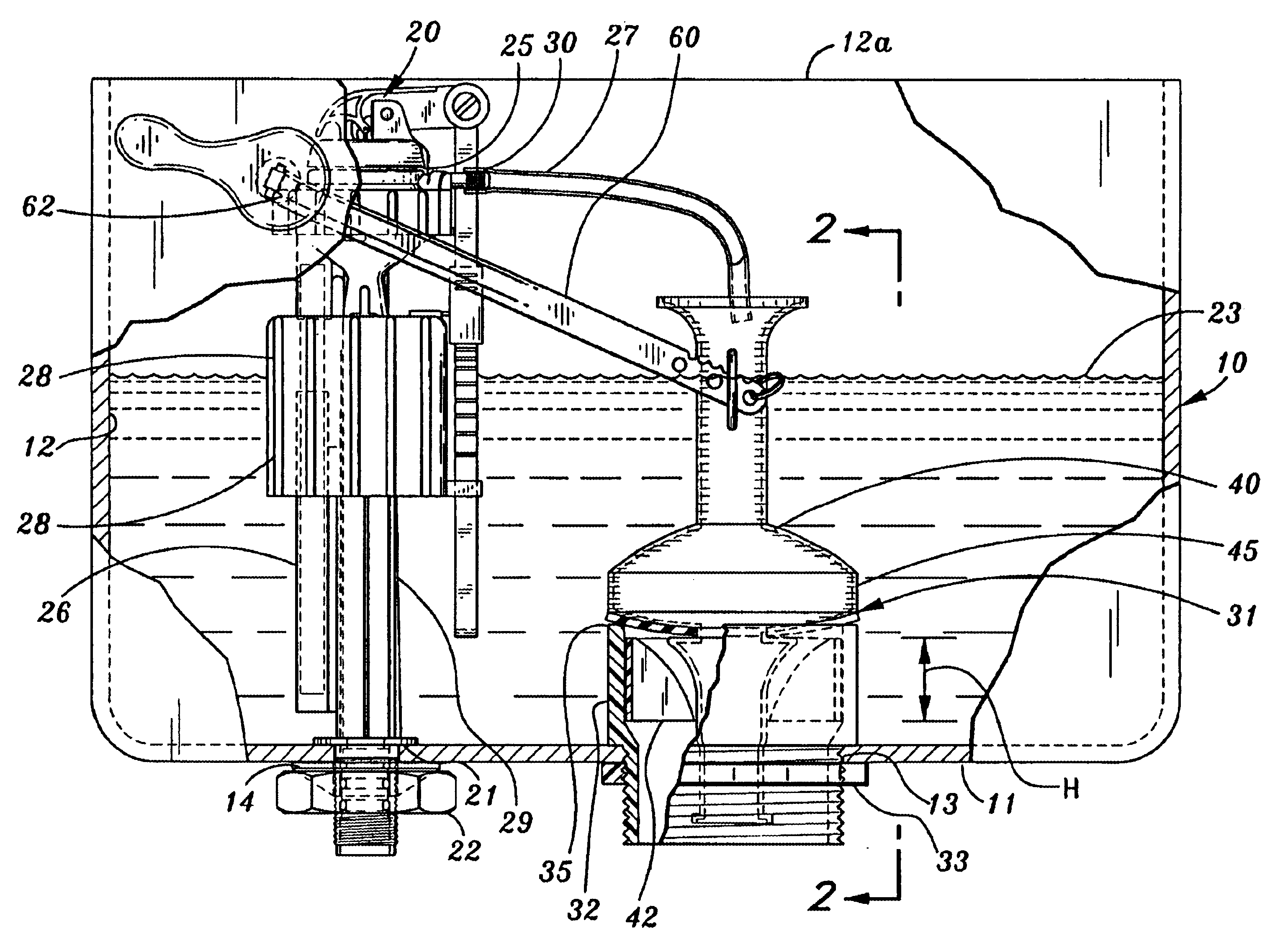
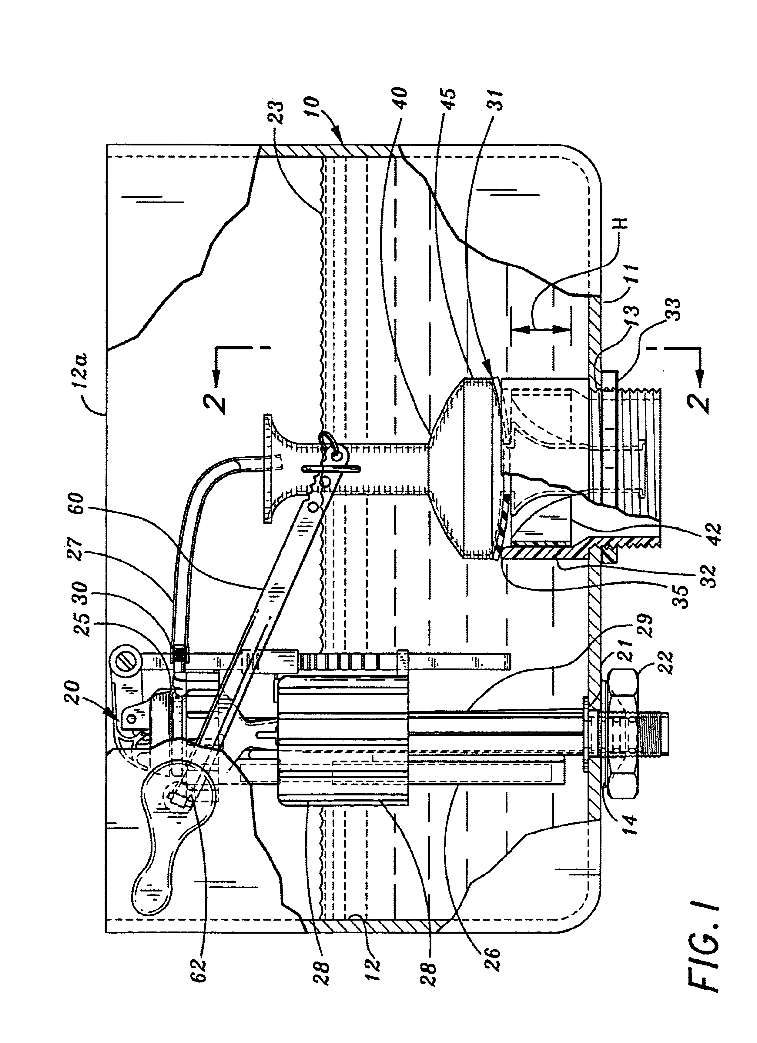
[0030]A toilet tank 10 has a bottom 11, a peripheral sidewall 12 and an open top 12a, which in use is covered by a removable lid (not shown). A central water discharge aperture 13 and an inlet aperture 14 are formed in the bottom of the tank.

[0031]A ballcock valve 20 is fitted in the inlet aperture by means of a typical spud 21 and nut 22. Any type of ballcock valve is suitable that provides the necessary functions of opening to flow when the water level 23 in the tank is below a predetermined elevation. At that time the valve workings 25 will supply water to the tank via a discharge tube 26, and to the toilet bowl through a bowl refill tube 27.

[0032]The illustrated valve is fully described in Antunez patent No. 6,244,292 which is incorporated herein in its entirety and made a part hereof by reference for its showing of the construction and operation of the valve workings.

[0033]A float 28 is wrapped partially around riser 29. Water under pressure is conveyed through the riser to the...


PUM


Abstract

A toilet tank flushing system including a ballcock valve for maintaining a storage level of water in the tank, a tank valve to release stored water on demand, and a linkage system which requires a reduced physical effort to initiate flushing. A hollow, open-ended closure for the tank valve enables a large cross-section area of discharge port to be used, and which can pass bowl refill water during the flushing sequence.

Description

FIELD OF THE INVENTION[0001]A fast-discharge, small volume toilet tank flush system.BACKGROUND OF THE INVENTION[0002]The advent of indoor plumbing and flush toilets, and decades of use and gradual improvement started with simple plug and flapper tank valves that were levered open, to remain open while a full tank emptied, and a ballcock valve which was open whenever the water level in the tank was below a storage level. While the ballcock valve was open, part of its total flow was diverted to refill the bowl at the same time the tank was being refilled. That procedure remains the same to this day for systems which use stored water to flush the toilet.[0003]Nearly every year there has been an improvement in some part of the conventional systems. Tank valves have evolved into many forms of pivoted plates and floats. Ballcock valves have evolved from simple floats on a lever that pressed on a valve plate, to differential pressure actuated valves that require movement by the float of on...

Claims


Application Information

Patent Timeline
Patent Type & Authority Patents(United States)
IPC IPC(8): E03D1/34E03D5/00E03D1/30E03D5/092
CPCE03D5/092E03D1/34
Inventor ANTUNEZ, BRUCE A.
Owner ANTUNEZ BRUCE A
Why Eureka
Try Eureka