Apparatus for removing a fastener from a workpiece

a technology for fasteners and workpieces, applied in the field of apparatus for removing fasteners, can solve the problems of limiting reducing the obvious value of fasteners, and the workpiece, and reducing the use of drift or punches. , to achieve the effect of reducing, if not eliminating, damage to the preventing damage to the threaded fastener and/or the workpi

Inactive Publication Date: 2005-06-28
THE BOEING CO
View PDF7 Cites 19 Cited by
  • Summary
  • Abstract
  • Description
  • Claims
  • Application Information

AI Technical Summary

Benefits of technology

[0010]An improved apparatus is provided according to embodiments of the present invention for removing a fastener, such as a bolt, a pin, a rivet or the like, from a corresponding aperture defined by a workpiece which reduces, if not eliminates, damage to the fastener and / or the workpiece that might otherwise be occasioned by conventional disassembly techniques. In this regard, the apparatus of embodiments of the present invention removes the fastener from the head end while maintaining a removal force that is in axial alignment with the fastener and centered on the corresponding aperture defined by the workpiece, thereby avoiding damage to the fastener and the workpiece. By removing the fastener from the head end, the apparatus can remove fasteners in situations in which the other end of the fastener is inaccessible with a drift or a punch. In addition, the apparatus of some embodiments of the present invention rotates the fastener as the fastener is removed from the corresponding aperture, thereby further preventing damage to threaded fasteners and / or threaded apertures, such as by thread scrubbing, during the removal process. In contrast, the apparatus of other embodiments removes the fastener without rotating the fastener, thereby avoiding enlarging the aperture such as in instances in which the fastener is bent, for example.
[0013]The lever member may therefore have a first end with a shape corresponding to the surface of the workpiece. For example, the first end of the lever member may be disposed at a non-orthogonal angle relative to the drive shaft. The first end of the lever member may include a flange or washer to spread the load over a larger area of the workpiece to avoid damaging the workpiece, a feature particularly attractive for workpieces formed of relatively soft materials. In addition, the first end of the lever may define a notch for accepting the head of another fastener or some other raised feature of the workpiece. The lever member of one embodiment includes an interchangeable end member to permit the shape of the first end to be selectively varied, typically based upon the shape of the workpiece. As such, the apparatus may be utilized in conjunction with workpieces of various shapes with the end member of the lever member generally being selected such that the first end of the lever member has a shape corresponding to that of the surface of the workpiece.
[0015]The lever member generally defines a cylindrical passage through which the drive shaft at least partially extends. Additionally, the lever member may include a collar defining an aperture for snugly receiving the drive shaft. By continuing to urge the lever member into operable contact with the surface of the workpiece while the fastener is being removed from the aperture and by maintaining the desired positional relationship between the lever member and the drive shaft, such as a result of the snug fit of the drive shaft within the aperture defined by the collar of the lever member, the apparatus of the present invention may remove the fastener while maintaining an axis of force centered on the aperture, perpendicular to the workpiece and in-line with the fastener being removed, thereby avoiding damage to the fastener or the aperture.
[0016]In one embodiment, the lever member and, most commonly, the collar of the lever member, is threadably connected to the drive shaft. According to one removal technique, the drive shaft may be threadably retracted in order move the pulling plug and, in turn, the head end of the fastener away from the surface of the workpiece, while the lever member remains in operable contact with the surface of the workpiece. In the embodiment in which the pulling plug includes a plurality of angularly disposed interior surfaces that define an interior cavity for receiving and mating with the polygonal head of a fastener, the threaded retraction of the drive shaft also rotates and threadably retracts the fastener. By threadably retracting the fastener, the apparatus of this embodiment further avoids damage to the fastener as well as any threaded aperture in which the fastener is installed. In order to facilitate the threaded retraction of the drive shaft, the drive shaft may be rotated by various means including turning the drive shaft with a wrench that engages a nut / lock nut combination that is mounted upon the drive shaft, or rotating the drive shaft with a drive tool.
[0019]Accordingly, the apparatus of the present invention permits fasteners to be removed from corresponding apertures defined by a workpiece with less risk of damaging the fasteners and the workpiece than conventional fastener removal techniques. In this regard, the apparatus generally maintains alignment between the fastener and the corresponding aperture during the process of removing the fastener. Additionally, the apparatus may threadably retract fasteners, such as threaded fasteners, in order to facilitate the removal of the fasteners from corresponding apertures defined by the workpiece and to further avoid damage, such as thread scrubbing, to the threaded fastener and / or correspondingly threaded apertures defined by the workpiece.

Problems solved by technology

Moreover, in instances in which fasteners are removed from a structure in order to perform life cycle testing or during an accident investigation, the evidentiary value of the fasteners, as well as the workpiece, is significantly diminished if the condition of the fastener and / or the workpiece is altered or damaged during the disassembly process.
Depending upon the design of the structure, however, the end of the fastener opposite the head end, such as the threaded end of a bolt, may be relatively inaccessible such that a drift or a punch cannot be utilized to push the fastener out of the corresponding aperture.
However, the surrounding structure oftentimes prevents access to the threaded end of the bolt with a drift or punch to thereafter remove the bolt.
Additionally, some structures may be at least partially forward of relatively soft material, such as aluminum, that may be damaged by the use of a drift or punch, thereby further limiting the use of a drift or punch.
In these instances, a drift or punch is also generally inappropriate since attempts to merely push the fastener out of the threaded aperture would be either ineffective and / or would damage the threads defined by the aperture and / or the fastener.
However, the force required to pull a fastener, such as a bolt, from the corresponding aperture may be substantial due, at least in part, to the generally snug fit of the fastener within the aperture.
Moreover, it is generally difficult to securely grasp the head end of the fastener and the vice grip, pliers or the like may tend to slip off if attempts are made to pull the fastener.
In addition, pulling a fastener from the corresponding aperture may damage the head end and / or threads of the fastener as well as the aperture.
For example, the pulling force applied to the fastener may serve to misalign the fastener relative to the aperture, thereby damaging the fastener and / or the aperture.
In these instances in which the fastener is damaged during its removal, the fastener must generally be replaced prior to reassembly of the structure.
Additionally, any apertures that were damaged during the disassembly process must be reworked prior to reassembly of the structure, thereby significantly increasing the time and expense associated with reassembling the structure.

Method used


Image

  • Apparatus for removing a fastener from a workpiece
  • Apparatus for removing a fastener from a workpiece
  • Apparatus for removing a fastener from a workpiece

Examples


Embodiment Construction

[0029]The present inventions now will be described more fully hereinafter with reference to the accompanying drawings, in which some, but not all embodiments of the invention are shown. Indeed, these inventions may be embodied in many different forms and should not be construed as limited to the embodiments set forth herein; rather, these embodiments are provided so that this disclosure will satisfy applicable legal requirements. Like numbers refer to like elements throughout.

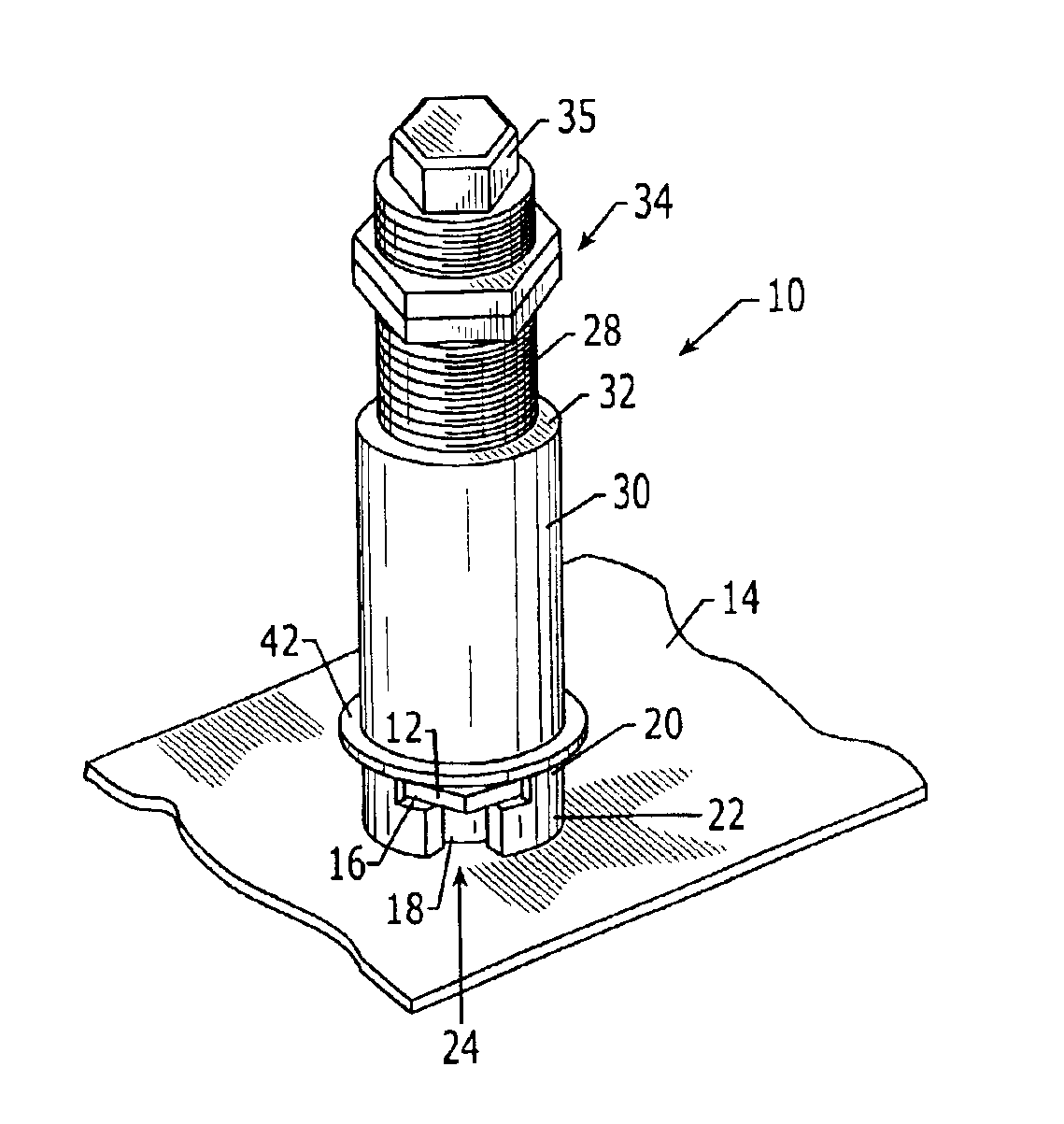
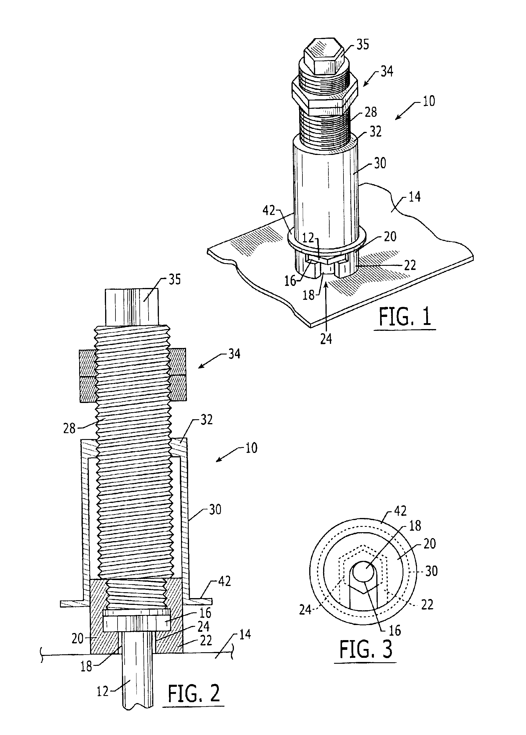
[0030]Referring now to FIG. 1, an apparatus 10 for removing a fastener 12 from a corresponding aperture defined by a workpiece 14 is depicted. The apparatus is capable of removing a variety of fasteners such as bolts, pins, rivets and the like. Regardless of the type of fastener, the fastener has a head end 16 that is accessible while the fastener is installed in the corresponding aperture defined by the workpiece. For example, the fastener may include a head end that sits upon or is recessed relative to the su...


PUM

PropertyMeasurementUnit
diameteraaaaaaaaaa
shapeaaaaaaaaaa
non-orthogonal angleaaaaaaaaaa

Abstract

An apparatus is provided for removing a fastener from a corresponding aperture defined by a workpiece that reduces or eliminates damage to the fastener and / or the workpiece. The apparatus includes a pulling plug for engaging the head of the fastener, and a drive shaft operably connected to the pulling plug. The apparatus further includes a lever member that is urged into operable contact with the workpiece. In operation, the head end of a fastener is engaged by the pulling plug. Thereafter, the lever member is moved into contact with the workpiece. The drive shaft is then retracted while the lever member continues to be urged into operable contact with and to push against the workpiece without positively engaging the workpiece. As such, the pulling plug is also moved away from the surface of the workpiece to remove the fastener from the workpiece.

Description

FIELD OF THE INVENTION[0001]The present invention relates generally to an apparatus for removing a fastener, such as a bolt, a pin, a rivet or the like, from a corresponding aperture defined by a workpiece and, more particularly, to an apparatus for removing a fastener from a workpiece without damaging the fastener or the workpiece which may be utilized in instances in which the fastener may only be accessed from the head end and, as a result, cannot be punched or pushed out.BACKGROUND OF THE INVENTION[0002]From time to time, fasteners, such as bolts, pins, rivets or the like, may need to be removed from various structures in order to partially or completely disassemble the structures. For example, various structures, including aircraft, undergo life cycle testing that requires at least some disassembly at one or more intervals during the lifetime of the structure. Additionally, structures that are involved in accidents may be disassembled during the investigation into the cause and...

Claims


Application Information

Patent Timeline
Patent Type & Authority Patents(United States)
IPC IPC(8): B25B27/02B21J15/50B21J15/00
CPCB21J15/50B25B27/023Y10T29/53878
Inventor DRAGGIE, RAYMOND Q.MAXWELL, SCOTT D.SMITH, DALE H.
Owner THE BOEING CO
Why Eureka
Try Eureka