Stiffener reinforced foldable member

a technology of reinforced foldable parts and stiffener, which is applied in the direction of transportation and packaging, aircrafts, and cosmonautic vehicles, can solve the problems of occupying a larger volume, and occupying internal voids. , to achieve the effect of compact folding

Inactive Publication Date: 2005-06-28
FOSTER-MILLER
View PDF142 Cites 29 Cited by
  • Summary
  • Abstract
  • Description
  • Claims
  • Application Information

AI Technical Summary

Benefits of technology

[0011]It is therefore an object of this invention to provide a tube which can be compactly folded and is thus useful in space applications and also in other applications.

Problems solved by technology

However, the internal void also means that the tube occupies much more volume than the volume of its constitutive material.
When the tubular structure needs to be transported for any reason, this means that the structure will occupy a larger volume that is strictly necessary.
When folded however, these tubular trusses remain as tubes and thus their internal voids still occupy volume during transport.
Inflatable structures have also been developed but inflatable structures, while exhibiting good packaging efficiency, unfortunately exhibit poor structural efficiency.
There is a limit, however, to the strength of such a device.
But, too thick in cross sectional area tube material makes it difficult to fold it especially without yielding the tube material and thicker tubes also makes it more difficult to unfurl or uncoil the tube material.

Method used


Image

  • Stiffener reinforced foldable member
  • Stiffener reinforced foldable member
  • Stiffener reinforced foldable member

Examples


Embodiment Construction

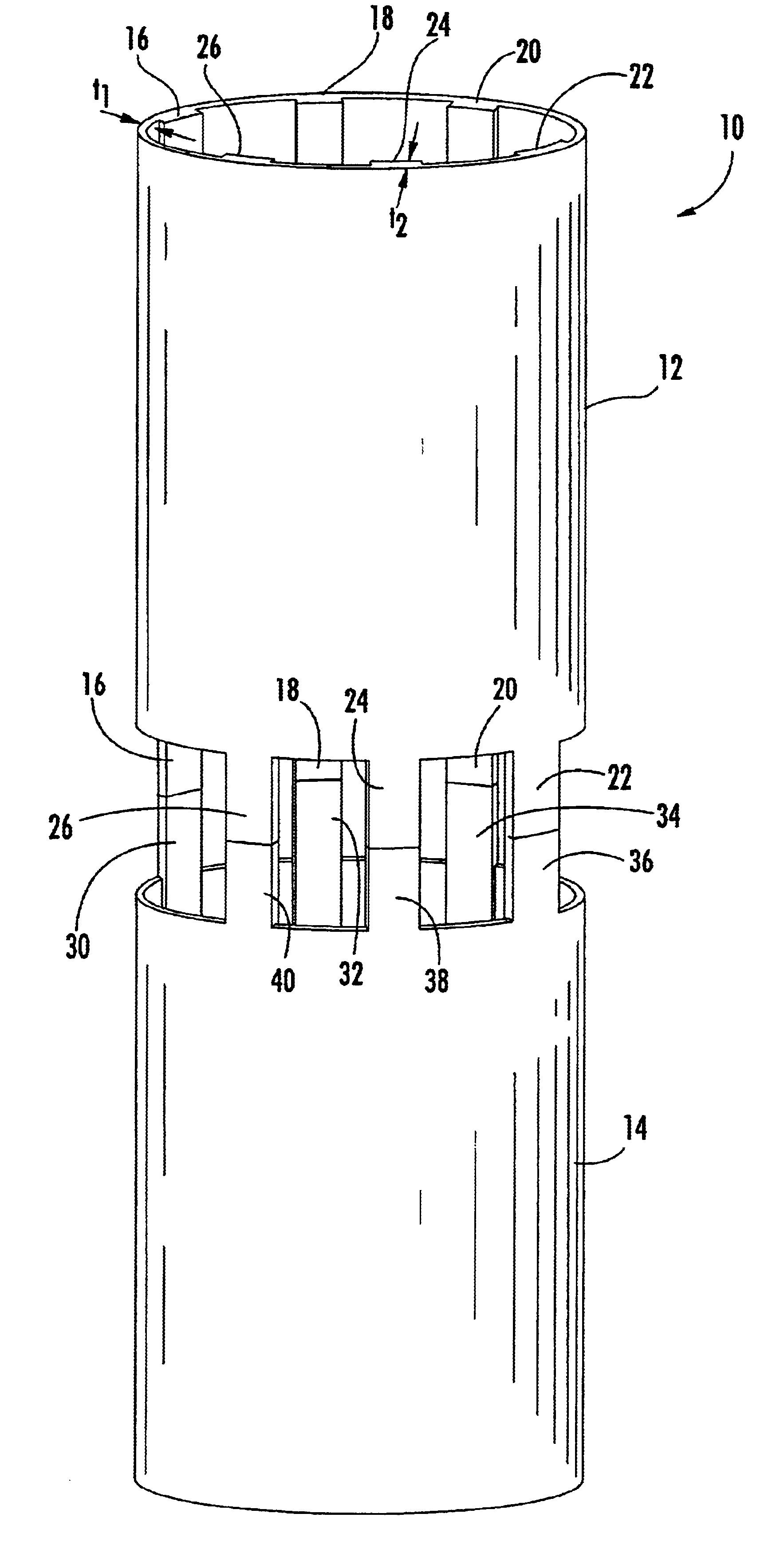
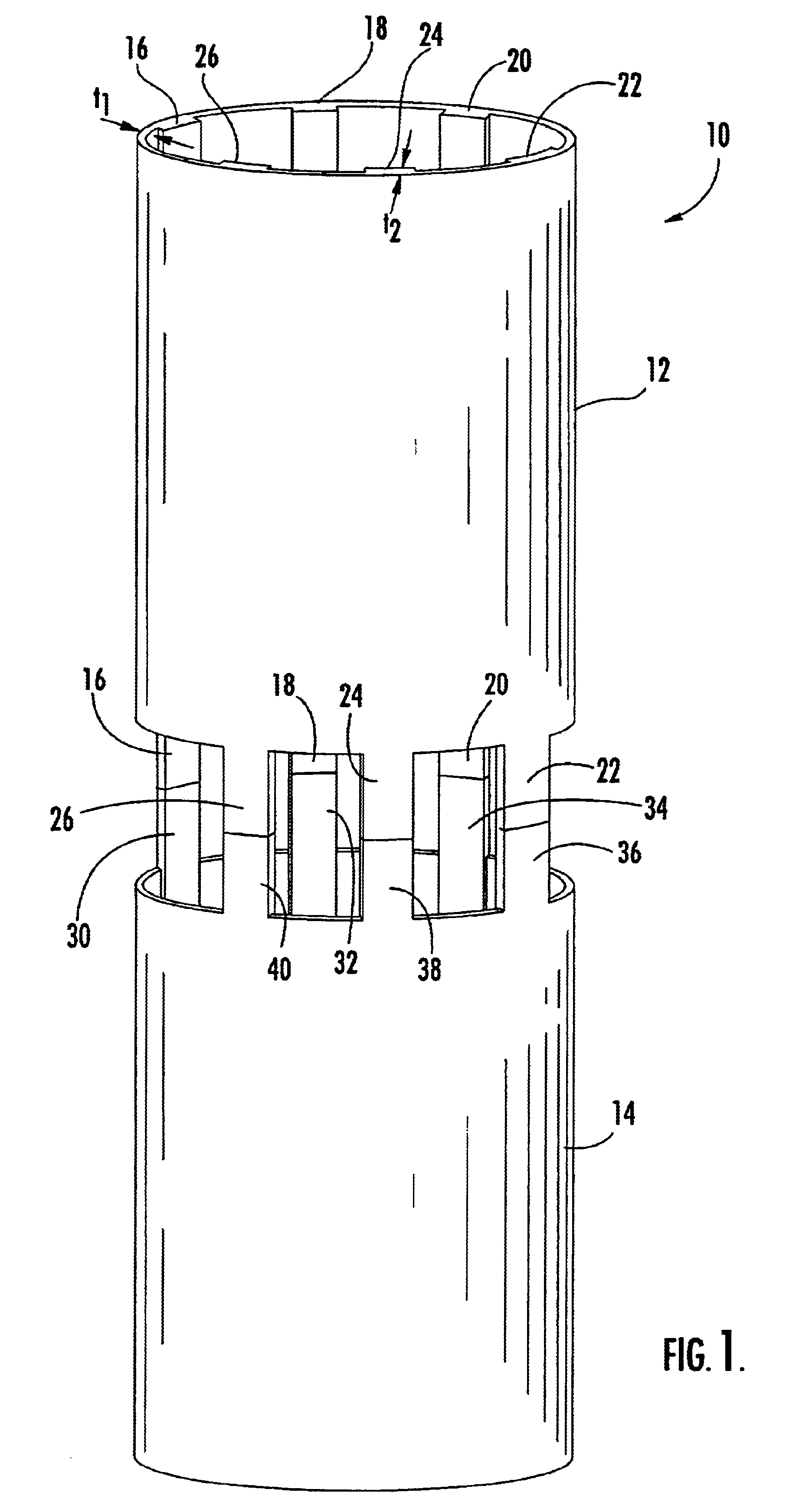
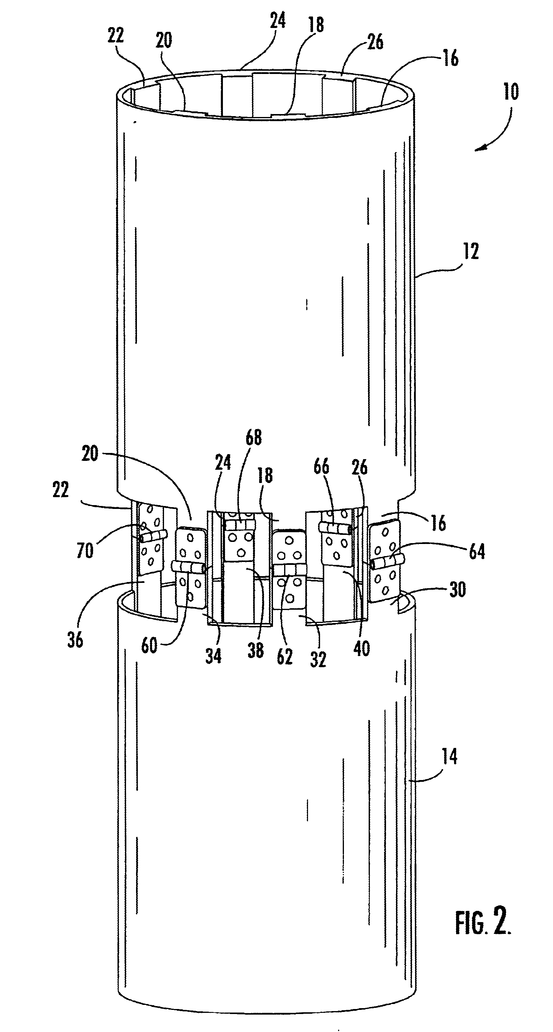
[0048]In one embodiment, foldable member 10, FIGS. 1-4 includes first 12 and second 14 longitudinally aligned tube sections made of a material which can be folded flat (see FIGS. 3-4) but biased to normally have an open construction or configuration as shown in FIGS. 1-2. One such material is composite material including carbon fibers and a resin matrix. Both sections 12 and 14 preferably include integral spaced longitudinally extending stiffeners also made of composite material. In, FIGS. 1-4, tube section 12 includes six stiffeners 16, 18, 20, 22, 24, and 26 and tube section 14 includes six stiffeners, 30, 32, 34, 36, 38, and 40. There is a hinged connection between tube sections 12 and 14 which, in this embodiment, includes discrete hinges connecting the stiffeners of section 12 and the corresponding stiffeners of section 14: hinge 60 hingedly interconnects stiffeners 20 of section 12 with stiffener 34 of section 14, hinge 62 interconnects stiffeners 18 and 32, hinge 64 interconn...


PUM


Abstract

A foldable member including a first structural section foldable flat and biased to have an open configuration and a second structural section also foldable flat and biased to have an open configuration. The second section is longitudinally aligned with the first structural section when both structural sections are in the open configuration. A hinged connection between the first and second structural sections allows the first structural section to be folded against the second structural section when both structural sections are folded flat.

Description

[0001]This application is a continuation-in-part application of application Ser. No. 10 / 114,236 filed of Apr. 2, 2002 now abn. That application is included herein by this reference.FIELD OF THE INVENTION[0002]This invention relates to a structure which can be compactly stored and then deployed to form a boom, truss, or longeron member, and collapsible trusses and other similar structures made of such members.BACKGROUND OF THE INVENTION[0003]Tubular columns are used for a wide variety of structural applications in which efficient structures are needed to support compressive loading, for example, in aerospace and space applications, e.g., the structures that supports solar arrays or communications antennae. See, e.g., U.S. Pat. No. 4,334,391 incorporated herein by this reference.[0004]Tubular columns are efficient because their large internal voids reduce their mass while maintaining their stiffness and strength. However, the internal void also means that the tube occupies much more v...

Claims


Application Information

Patent Timeline
Patent Type & Authority Patents(United States)
IPC IPC(8): B64G1/22E04C3/00E04BE04B1/344E04H3/28E04H12/18
CPCB64G1/222E04B1/3441E04H12/187E04H3/28E04C3/005
Inventor WARREN, PETER A.
Owner FOSTER-MILLER
Why Eureka
Try Eureka