Out-of-plane compensation suspension for an accelerometer

a technology of accelerometer and compensation suspension, which is applied in the direction of acceleration measurement using interia forces, instruments, force/torque/work measurement, etc., can solve the problems of reducing the inter-finger capacitance and the applied force, and achieve the effect of reducing or eliminating the out-of-plane separation

Inactive Publication Date: 2005-06-28
HONEYWELL INT INC
View PDF4 Cites 32 Cited by
  • Summary
  • Abstract
  • Description
  • Claims
  • Application Information

AI Technical Summary

Benefits of technology

[0009]The present invention substantially reduces or eliminates the out-of-plane separation or de-meshing of the device fingers the resulting cross-axis sensitivity by suspending the traditionally fixed electrode structure so that, while substantially fixed against motion in the sensitive axis and in-plane cross-axis directions, the electrode structure is responsive to a force applied out-of-plane to move out-of-plane in a direction and by an amount substantially the same as those of the proof mass.

Problems solved by technology

One problem with such capacitive readout in-plane accelerometers is that, when fabricated as HIMEMS devices, forces applied out-of-plane relative to the intermeshing fingers causes out-of-plane separation or “de-meshing” of the fingers, which decreases the inter-finger capacitance and registers as a decrease in the applied force or acceleration.

Method used


Image

  • Out-of-plane compensation suspension for an accelerometer
  • Out-of-plane compensation suspension for an accelerometer
  • Out-of-plane compensation suspension for an accelerometer

Examples


Embodiment Construction

[0020]In the Figures, like numerals indicate like elements.

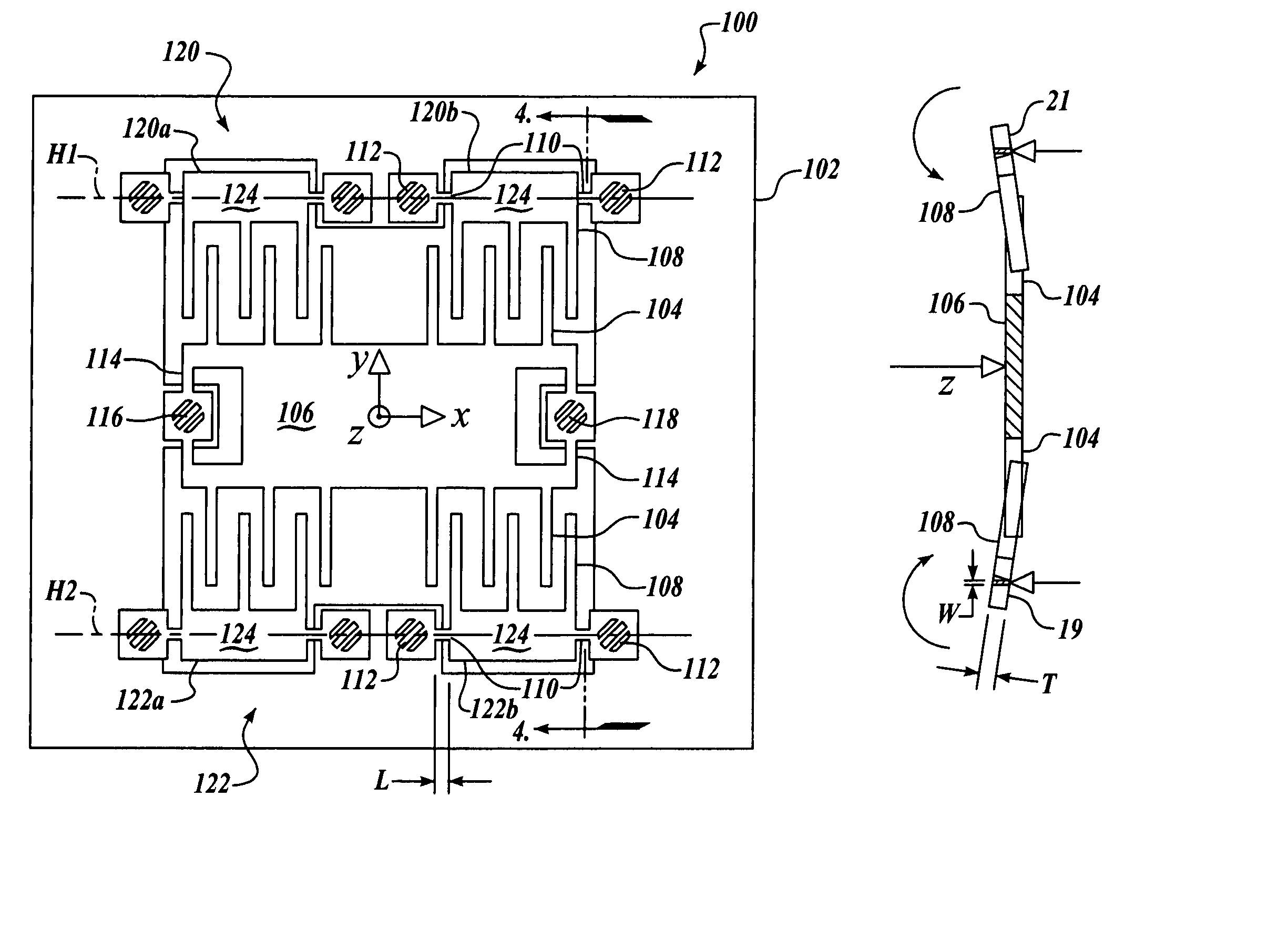
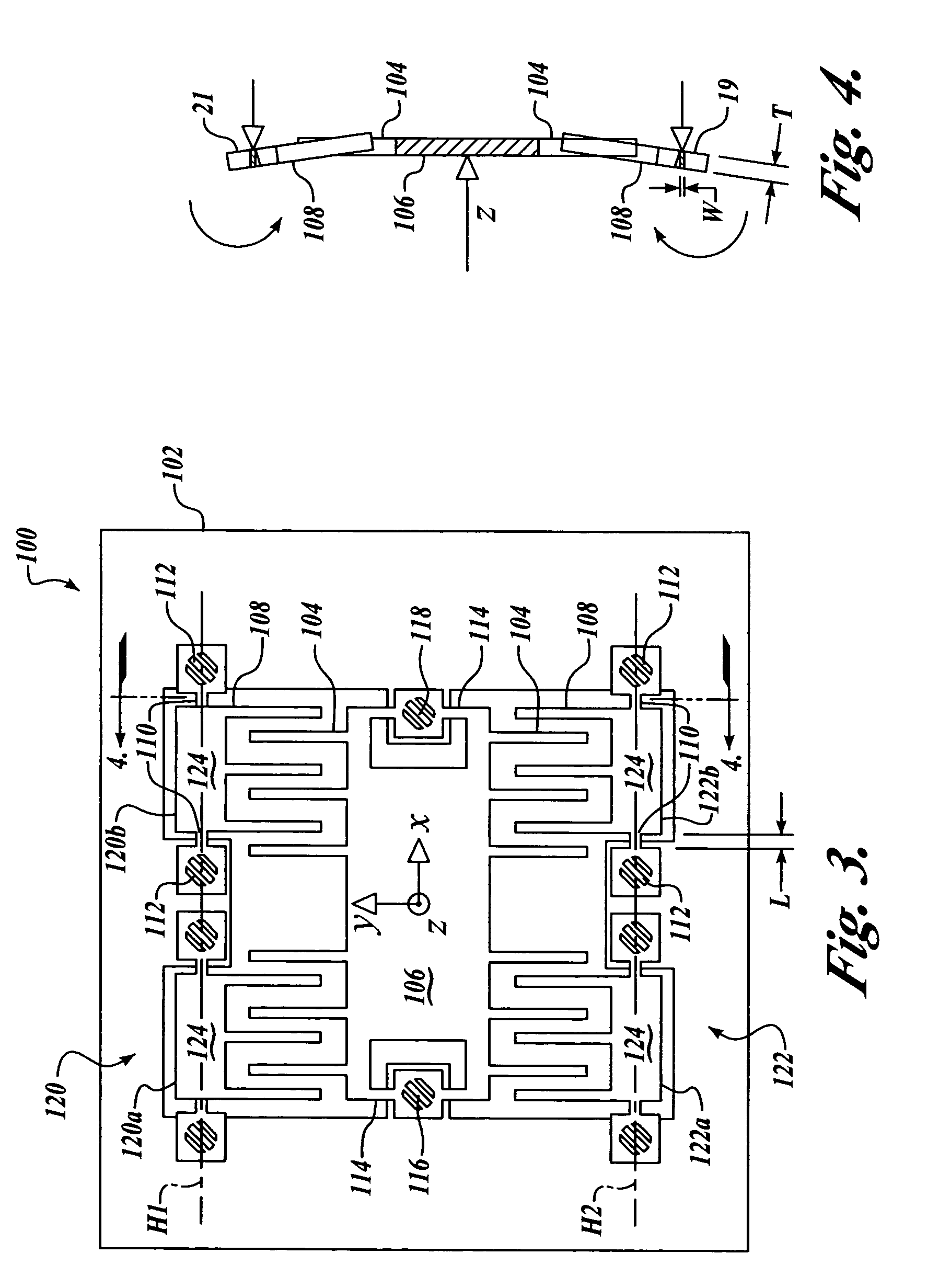
[0021]The present invention is a suspension apparatus and method for compensating out-of-plane displacements of a proof mass in an in-plane comb-type capacitive readout force transducer fabricated as a high aspect ratio MEMS or HIMEMS device for measuring an applied force, such as an accelerometer, wherein the HIMEMS device includes an instrument frame forming a part of the framework of the transducer;[0022]a substrate of substantially uniform thickness having formed therein a proof mass of substantially uniform width and being suspended by one or more flexures at each of two opposing ends for motion relative to the frame in the plane of the substrate and along an axis crosswise to its width, the proof mass having on each of two edges spaced apart by its width a quantity of outwardly projected fingers spaced along its length and aligned substantially crosswise to its axis of motion and forming individual substantially planar...


PUM


Abstract

A high aspect ratio microelectromechanical system device for measuring an applied force and having a suspension structure for compensating out-of-plane displacements of the device proof mass, wherein the device includes a frame; a proof mass coupled to the frame for in-plane motion along an axis of symmetry, the proof mass having first and second sets of spaced apart capacitor plates projected therefrom on each side of the axis of symmetry and oriented substantially crosswise to the axis of symmetry; and third and fourth sets of spaced apart capacitor plates oriented substantially crosswise to the axis of symmetry of the proof mass and intermeshed respectively with the first and second sets of capacitor plates, the third and fourth sets of capacitor plates being suspended for motion relative to the frame about respective first and second axes of motion oriented substantially parallel with the axis of symmetry of the proof mass.

Description

FIELD OF THE INVENTION[0001]The present invention relates to micromachined accelerometer devices, and in particular to suspension structures for compensating out-of-plane displacements of the proof mass of micro-machined accelerometers incorporating one or more comb-type capacitive readout force transducers for measuring the force applied to a proof mass and methods for manufacturing the same.BACKGROUND OF THE INVENTION[0002]A widely used technique for force detection and measurement employs a mechanical capacitive readout force transducer having a capacitive output proportional to the force applied. In one such mechanical transducer, one or more capacitors are formed between an instrument frame and a proof mass suspended by a flexure. A force applied to the proof mass along a particular axis will cause displacement of the proof mass relative to the frame, which varies the capacitive output of the capacitors. The force applied to the proof mass is quantified by measuring a resultant...

Claims


Application Information

Patent Timeline
Patent Type & Authority Patents(United States)
IPC IPC(8): B81B3/00G01P15/08G01P15/125
CPCB81B3/0062G01P15/125G01P15/0802B81B2201/0235
Inventor ESKRIDGE, MARK H.BALLAS, GARY J.
Owner HONEYWELL INT INC
Why Eureka
Try Eureka