
Mechanism that assists tractoring on uniform and non-uniform surfaces

Inactive Publication Date: 2005-06-28
SCHLUMBERGER TECH CORP
View PDF61 Cites 68 Cited by
  • Summary
  • Abstract
  • Description
  • Claims
  • Application Information

AI Technical Summary

Benefits of technology

[0006]It is a principal feature of the present invention to provide a novel linkage mechanism that is utilized in conjunction with or as a component of a tractor mechanism to enhance the traction capability of the tractor mechanism when deviations in internal wall surfaces are encountered;
[0007]It is another feature of the present invention to provide a novel six-bar type linkage mechanism that offers minimal resistance to movement along the internal surface of a borehole or conduit; and
[0008]It is also a feature of the present invention to provide a novel six-bar type linkage mechanism that becomes essentially conformed to the internal configuration of the wellbore, well casing, or pipeline that is being traversed and thus maintains an efficient traction capability with the non-uniform internal surface and, after passing an anomaly on the surface, returns to a predetermined configuration for a uniform internal surface.
[0009]Briefly, the various principles of the present invention are realized in general by a six-bar linkage mechanism that is employed in conjunction with a tractoring mechanism to assist the tractoring mechanism and other systems to accomplish efficient traction movement within internal surfaces of both uniform and non-uniform surface character. The six-bar linkage mechanism of the present invention is constructed in such a manner that the bars pivot around their joints in order to adapt the linkage mechanism to assume variations in its configuration responsive to the changes of the internal surface geometry in which the system is being utilized to assist or enhance tractoring capability of the systems by maintaining efficient traction contact with the internal surface regardless of its geometric changes.
[0010]Specifically, the design relates to logging tools or other tools or devices that are intended to be conveyed through the boreholes of oil and gas wells or conveyed through pipes, such as well casings or pipelines. The present invention may be utilized in conjunction with downhole tractors for well casings in order to facilitate the passage of traction devices and the well tools conveyed thereby over casing joints, restrictions, changes in pipe diameter, and other internal wall surface irregularities in pipes. The six-bar linkage mechanism may also be utilized for traction activity in open-hole wellbores where the density and hardness of the walls allow its utilization. The six-bar linkage mechanism improves other designs and allows the utilization of different types of downhole tractors that otherwise would not be able to move through non-uniform surfaces in casing or open-hole wellbores. The six-bar linkage mechanism of the present invention is also applicable for utilization as a component of a centralizer mechanism for oilfield tools such as logging tools, perforating guns, or other tools that require specific centralized location within a wellbore.

Problems solved by technology

The disadvantage of this mechanism for tractoring is that the force required to push it through casing joints is several times higher than that required with the six-bar mechanism utilized in the present invention.
If used to assist tractoring systems, the rollers of this well tool mechanism will enter casing joints and other depressions and almost always become caught in most casing joints.
This system will not allow tractoring systems to pass casing joints and changes of pipe diameter while simultaneously tractoring.

Method used


Image

  • Mechanism that assists tractoring on uniform and non-uniform surfaces
  • Mechanism that assists tractoring on uniform and non-uniform surfaces
  • Mechanism that assists tractoring on uniform and non-uniform surfaces

Examples


Embodiment Construction

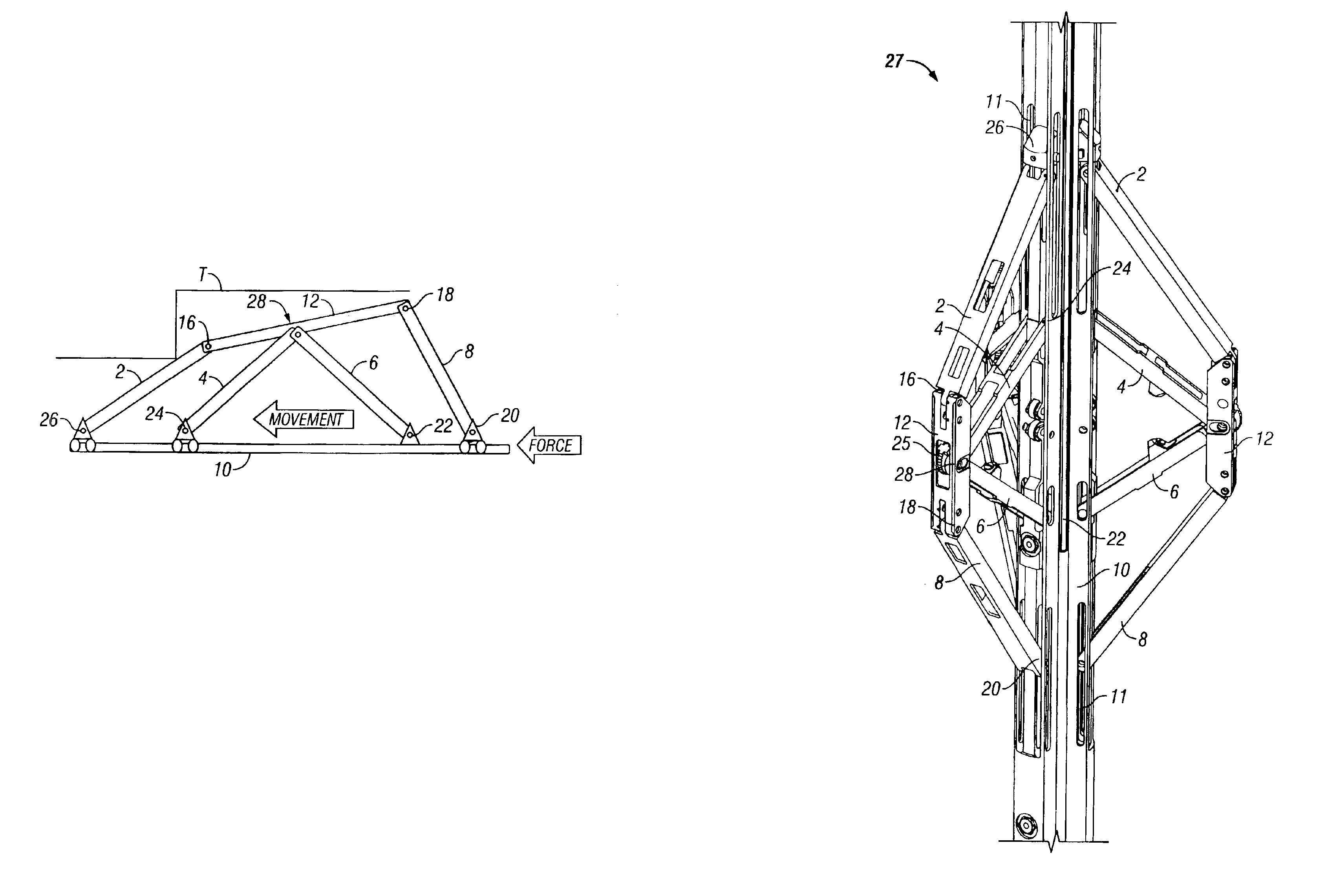
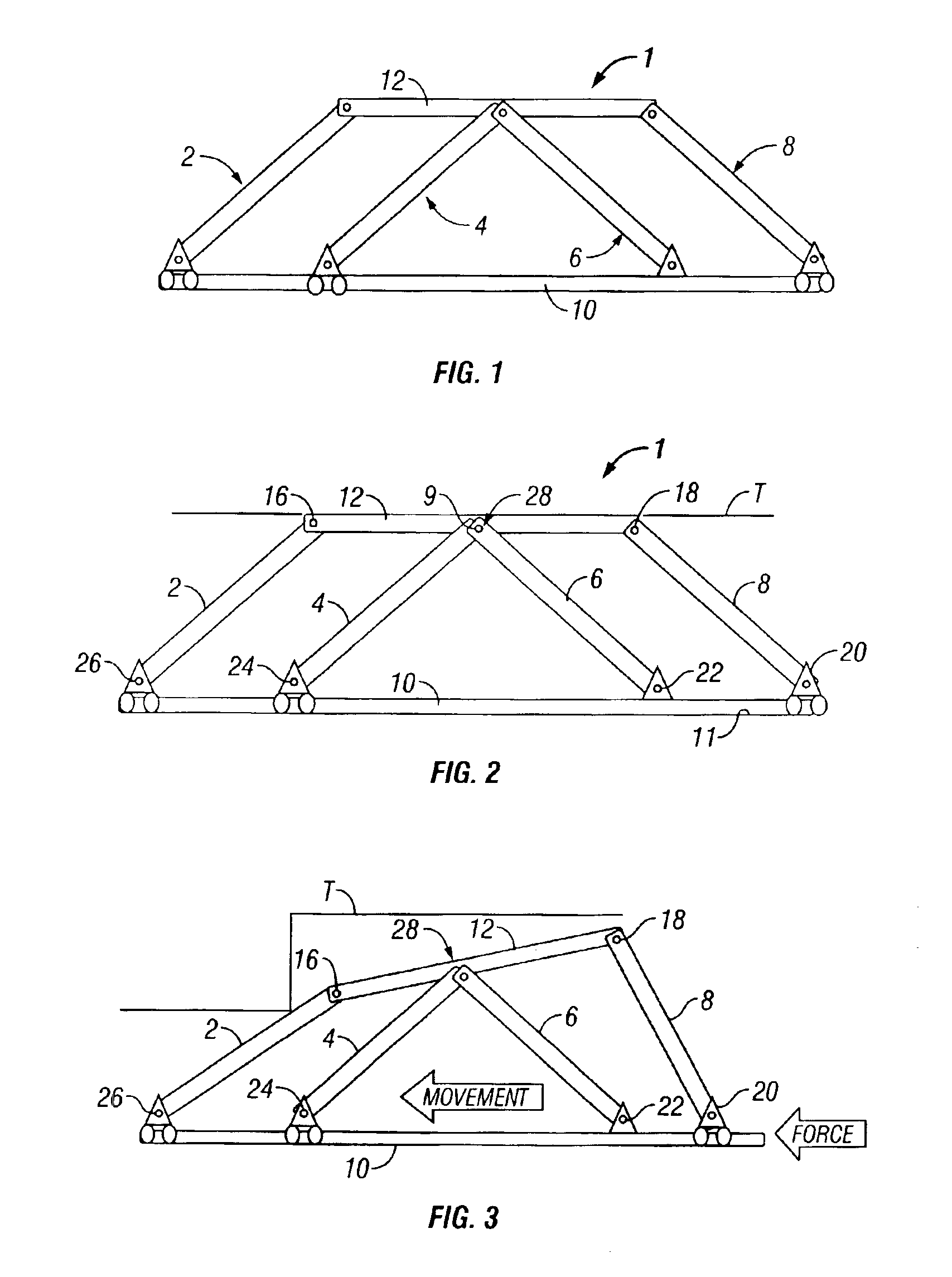
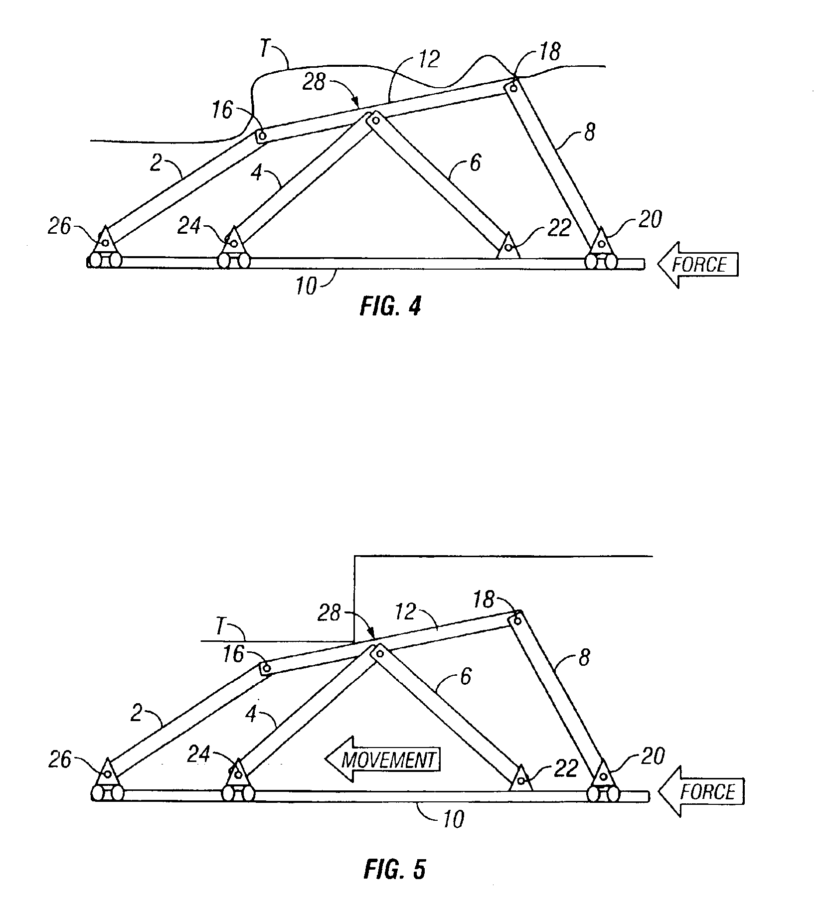
[0023]Referring now to the drawings and first to FIGS. 1 and 2, a six-bar linkage mechanism constructed according to the principles of the present invention is shown generally at 1 and incorporates a pair of centralizer links 4 and 6 each having upper and lower ends with the upper ends thereof being connected to a saddle link 12 and the lower ends thereof connected to a central link 10. Though the centralizer links and the central link may be of any desired configuration, depending upon the tool mechanism with which they are associated, for purposes of explanation, they, and other links of the six bar linkage mechanism, are shown as elongate substantially straight members. The centralizer link 6 is pivotally connected to the central link 10 and thus can only pivot with respect to the central link 10 around a pivot joint 22 having a pivot that is fixed to the central link 10 at a point intermediate the extremities of the central link 10. Thus, the pivot joint 22 is referred to herein...


PUM


Abstract

A six-bar linkage mechanism for conforming to the configuration of a tractored surface having a central link defined by a tool body and a saddle link spaced from the central link and movable for conforming with the tractored surface. A pair of front links each having pivotal connection with respective ends of the saddle link and having linearly movable pivotal connection with the central link to permit angular and spacing changes of the saddle link relative to the central link. A pair of centralizer links are located between the front links and have pivotal connections with the saddle link and pivotal connections with the central link. One of the pivotal connections is linearly movable on the central link. For tractor tools, when the tractored surface is a wellbore or well pipe, a plurality of six-bar linkages radiate from a tool body for surface conforming traction with the tractored surface.

Description

CROSS-REFERENCE TO RELATED APPLICATIONS[0001]This application claims priority from U.S. Provisional Application No. 60 / 369,385, filed Apr. 2, 2002, which is incorporated herein by reference.BACKGROUND OF THE INVENTION[0002]1. Field of the Invention[0003]The present invention relates generally to tractoring mechanisms for use in wells. More particularly, the present invention relates to a mechanism that assists tractoring in wells having uniform and non-uniform surfaces by adjusting or adapting its configuration in response to the internal surface configuration of the wellbore, well casing, or pipe through which it is moved. Even more particularly, the present invention is particularly applicable to the field of borehole tractors for conveying logging and service tools in deviated or horizontal oil and gas wells, or in pipelines, where such tools may not readily be conveyed by the force of gravity.[0004]2. Description of Related Art[0005]U.S. Pat. No. 4,557,327 discloses a roller arm...

Claims


Application Information

Patent Timeline
IPC IPC(8): E21B23/14E21B17/00E21B17/10E21B23/00
CPCE21B17/1021E21B23/14Y10T74/18928E21B2023/008E21B23/001
Inventor GUERRERO, JULIO C.
Owner SCHLUMBERGER TECH CORP
Learn More