Thread-forming screw

a thread-forming screw and thread-forming technology, applied in the direction of thread-forming fasteners, screws, fastening means, etc., can solve the problems of undesired release of thread-forming screws, loosening of screws from workpieces, and relatively high application costs of micro capsules, so as to achieve maximum safety against undesired release

Inactive Publication Date: 2005-06-28
ITW AUTOMOTIVE PRODS
View PDF15 Cites 17 Cited by
  • Summary
  • Abstract
  • Description
  • Claims
  • Application Information

AI Technical Summary

Benefits of technology

[0005]With the invention, a thread-forming screw is to be provided which in the pre-assembled and also in the finally assembled state guarantees a maximum safety against undesired release.

Problems solved by technology

Threaded connections with thread-forming screws suffer under undesired release, for example by vibrations.
During transportation of such pre-assembled units vibration may occur which may lead to a loosening of the screws from the workpieces.
However, the application of such micro capsules is relatively expensive.

Method used


Image

  • Thread-forming screw
  • Thread-forming screw

Examples


Embodiment Construction

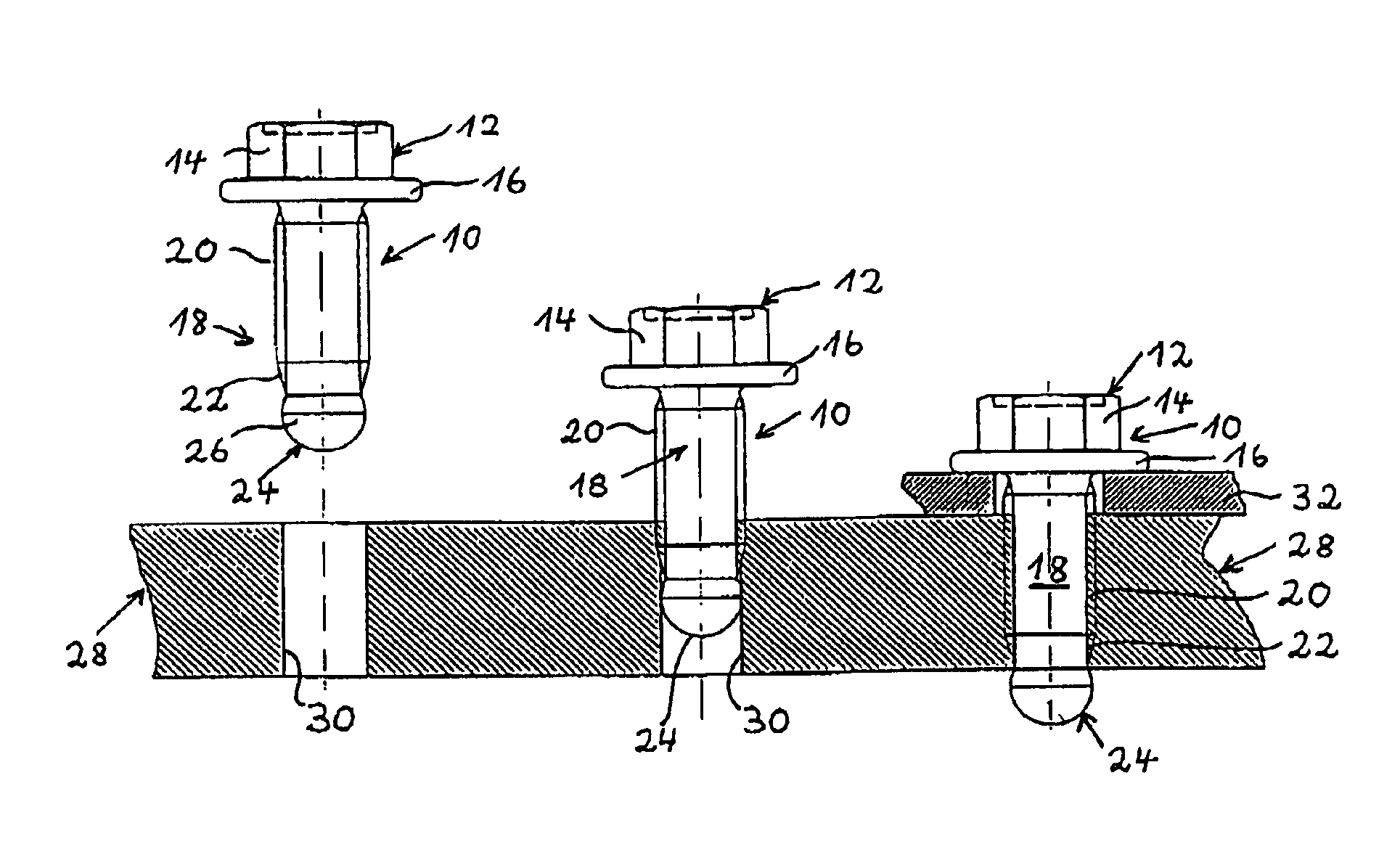
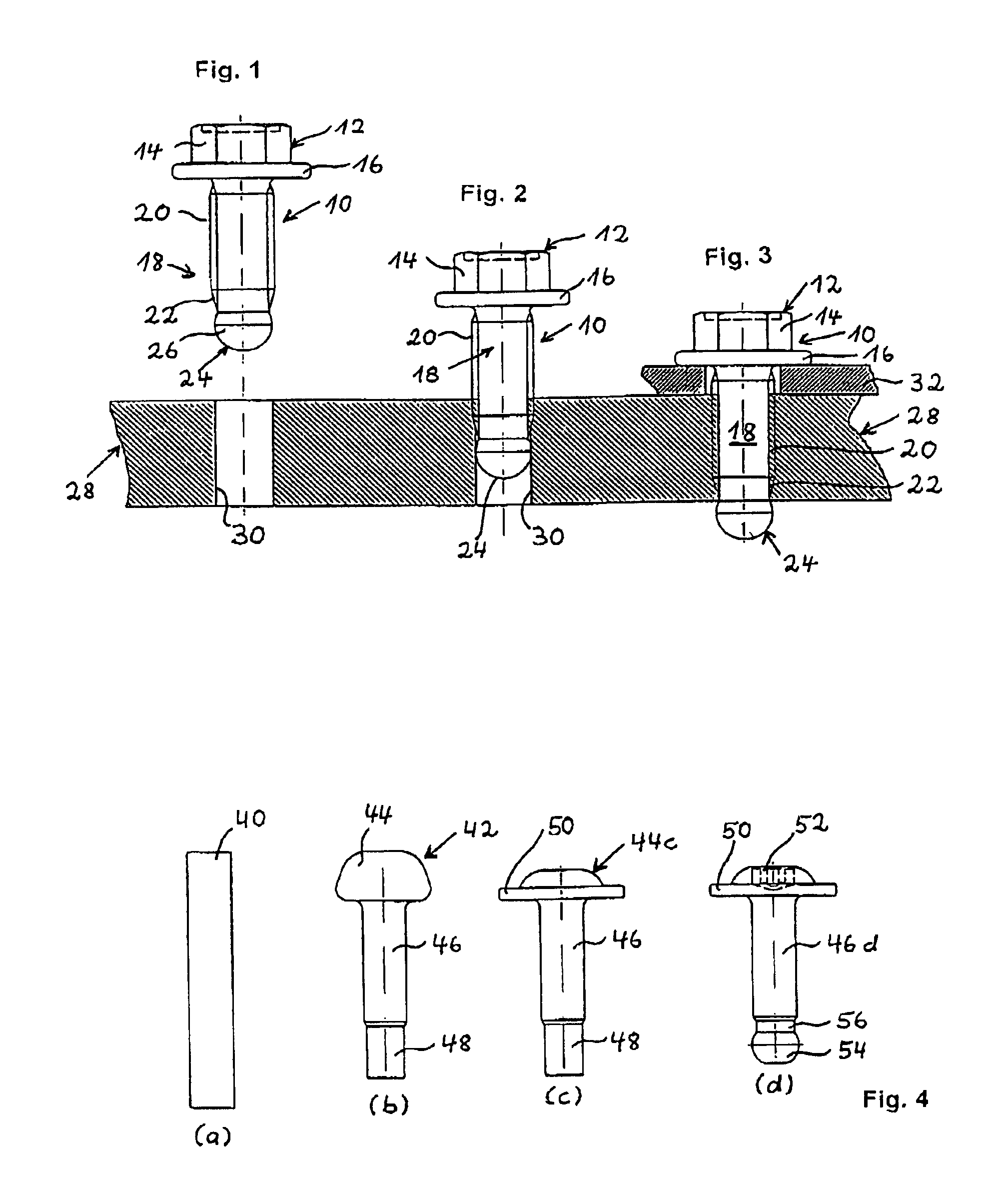
[0017]In FIGS. 1 to 3, a thread-forming screw 10 is depicted. It includes a head 12 with a hexagon 14 and a flange 16 adjacent thereto. The screw 10 includes further a shank 18 provided with a thread. In the end portion of thread 20 a thread-forming zone is provided having a conical portion 22. A spherical portion 24 joins to conical portion 22. The diameter of the spherical portion 24 immediately adjacent the conical portion 22 corresponds to the diameter of the conical portion at this location. The maximum diameter of the spherical portion shown at 26 corresponds to the pitch thread diameter of thread 20.

[0018]In FIGS. 1 to 3 there is shown a workpiece 28 of plastic material. It includes a throughbore 30 having a diameter which corresponds to the pitch diameter of thread 20.

[0019]In the illustration of FIG. 2 it is shown that the thread-forming screw is partially threaded into bore 30. By means of the thread-forming zone (not shown in detail), a thread is formed in the wall of bor...


PUM

PropertyMeasurementUnit
diameteraaaaaaaaaa
lengthaaaaaaaaaa
plastic deformationaaaaaaaaaa

Abstract

A thread-forming screw includes a head and a shank, the shank having a thread and a thread-forming zone at the end opposite to the head, the thread-forming zone also having a thread portion. The shank at the end opposite to the head has a spherical portion with a maximum diameter in a plane perpendicular to the axis of the shank which corresponds approximately to the mean diameter of the thread of the shank.

Description

TECHNICAL FIELD[0001]The invention refers to a thread-forming screw.BACKGROUND ART[0002]Thread-forming screws typically are screws having a thread adapted to produce a counter or female thread in a bore of a workpiece. Usually, one differentiates between a tapping and forming thread of a screw. In case of a tapping thread a counter thread is produced in a preformed hole by a chip-generating forming process. In case of a self-forming thread the counter thread is generated substantially without chips through a plastic deformation of the workpiece. In this connection it is known to provide self-forming screws with a thread-generating zone by which particularly effectively a counter thread can be produced. If the workpieces are made of plastic material, the preformed hole or the preformed bore normally has not the core or root diameter of the thread-forming screw, rather, is provided with a greater diameter, preferably with the thread pitch diameter of the thread-forming screw.[0003]For...

Claims


Application Information

Patent Timeline
Patent Type & Authority Patents(United States)
IPC IPC(8): F16B25/00
CPCF16B25/0015
Inventor ISENBERG, RAINER
Owner ITW AUTOMOTIVE PRODS
Why Eureka
Try Eureka