
Twist on orthodontic hook

a hook and hook technology, applied in the field of orthodontic assembly, can solve the problems of difficult to ensure the cleanliness of the arch wire, the difficulty of the hook to be attached to the arch at locations, and the movement of soldered or electro-welded arch wire hooks in the mouth

Inactive Publication Date: 2005-06-28
BLOORE JOHN A +1
View PDF3 Cites 6 Cited by
  • Summary
  • Abstract
  • Description
  • Claims
  • Application Information

AI Technical Summary

Benefits of technology

[0010]The present invention is directed to an orthodontic hook attached to an orthodontic appliance for the attachment of a elastics, elastomeric modules, springs, cables, and ligature wires. Specifically the invention is designed to be attached to an orthodontic bracket producing a hook and, most importantly, the absence of a ligature end which must be cut and tucked in. A further object of the orthodontic hook is ease of installation, no special mounting to the orthodontic bracket or welding or soldering to the orthodontic arch wire is required. Another object is to provide a mounting which is strong and retained in place securely. An additional object is to provide a hook which can be Installed on the orthodontic appliance in any chosen position. A final object is easy removal of the hook; it is removed as easily as a ligature be wire.

Problems solved by technology

If the manufacturer places the hooks it is difficult for the hooks to be attached to an arch at locations best suited for a particular patient.
The movement of soldered or electro-welded arch wires hooks which have been in the mouth is further complicated by the fact the wire must be absolutely clean in order to place a new hook.
Cleanliness is difficult to assure for an arch wire that has been in the mouth any appreciable length of time.
A principal difficulty with such a hook mounting is that it is necessary to hold the cap in place on the bracket while bending the retaining tabs to engage the bracket, which also may exert force on the bracket.
Bending of the tabs to remove the hook mounting may additionally exert force on the bracket.
The set screws tend to loosen in the mouth.
The disadvantage of this type of hook is the orthodontist must predict the locations hooks will be needed during treatment at the time the braces are installed.
The need for hooks in certain areas usually develops during treatment and initially placing hooks everywhere may be more uncomfortable for the patient along with more difficult oral hygiene.

Method used


Image

  • Twist on orthodontic hook
  • Twist on orthodontic hook
  • Twist on orthodontic hook

Examples


Embodiment Construction

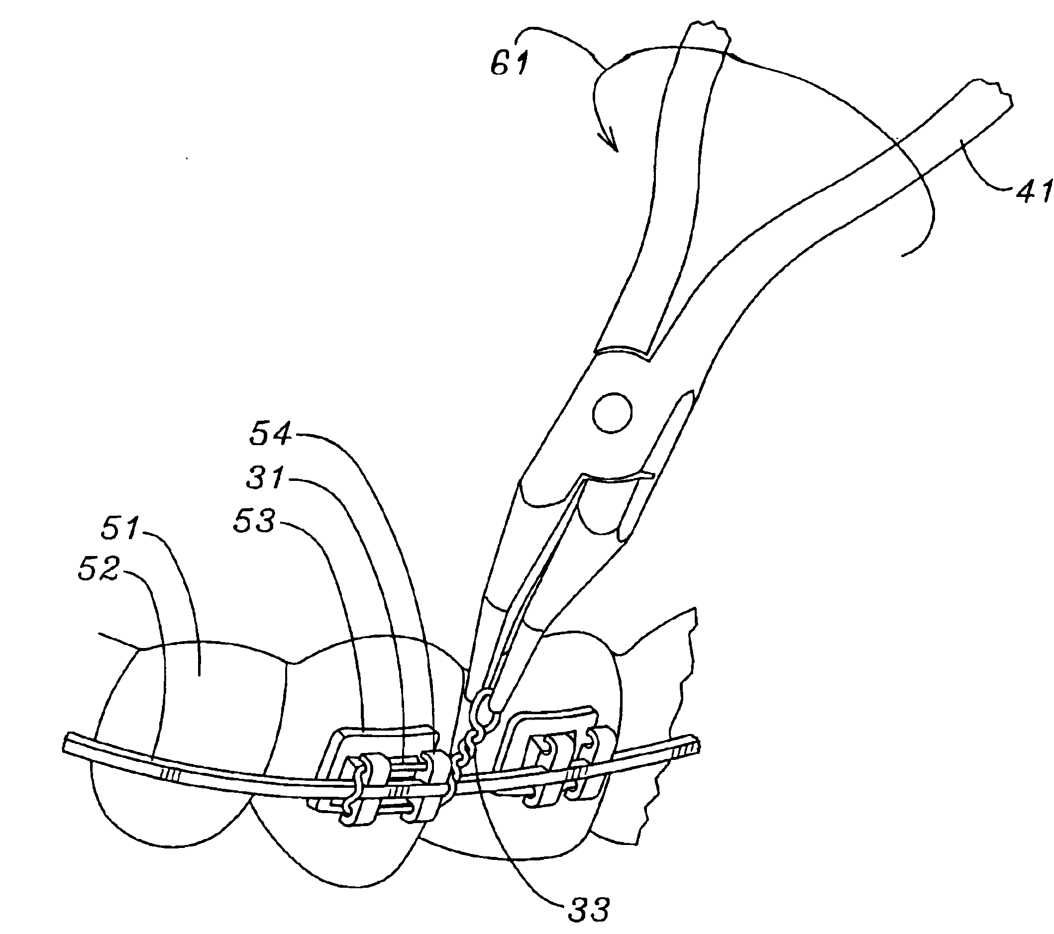
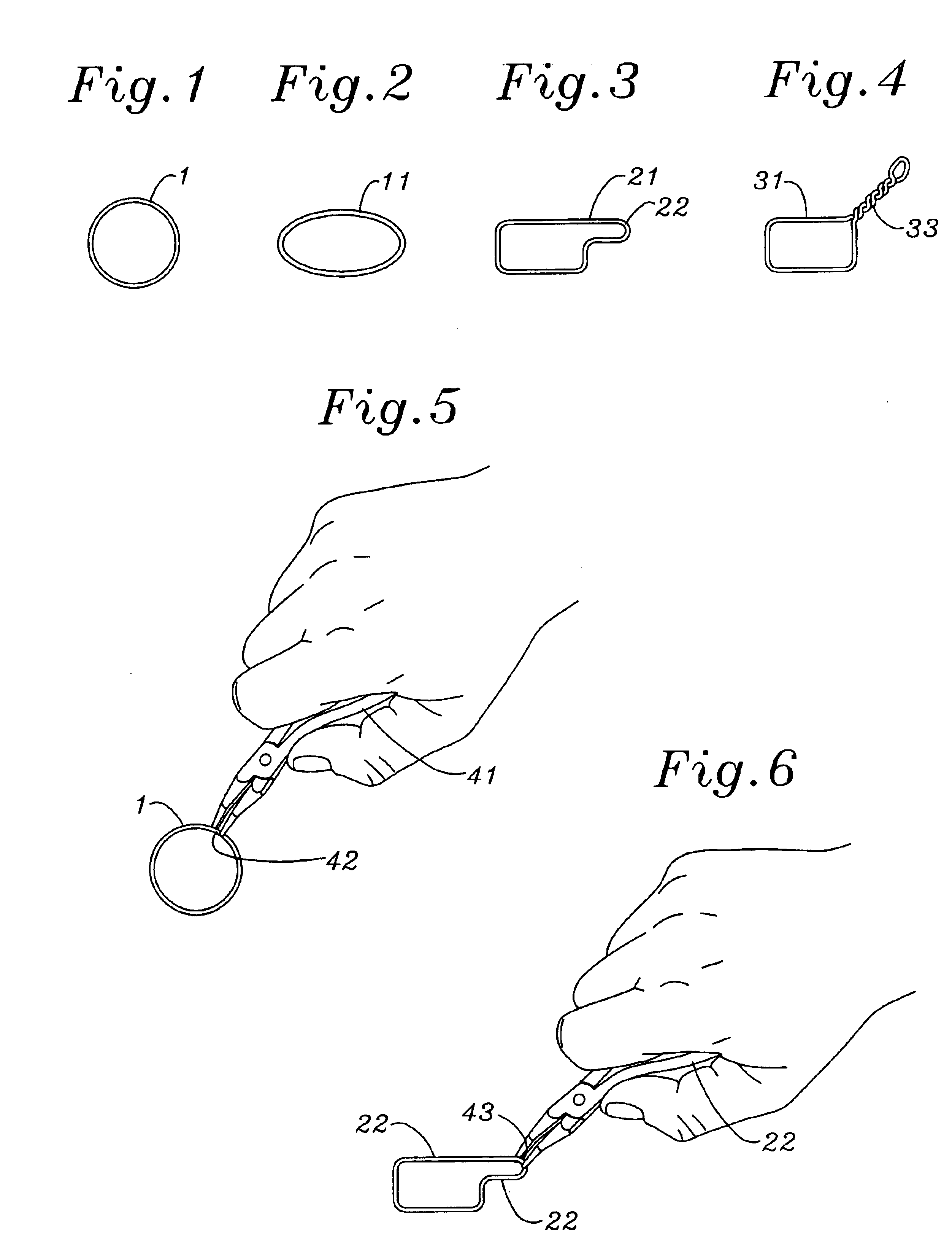
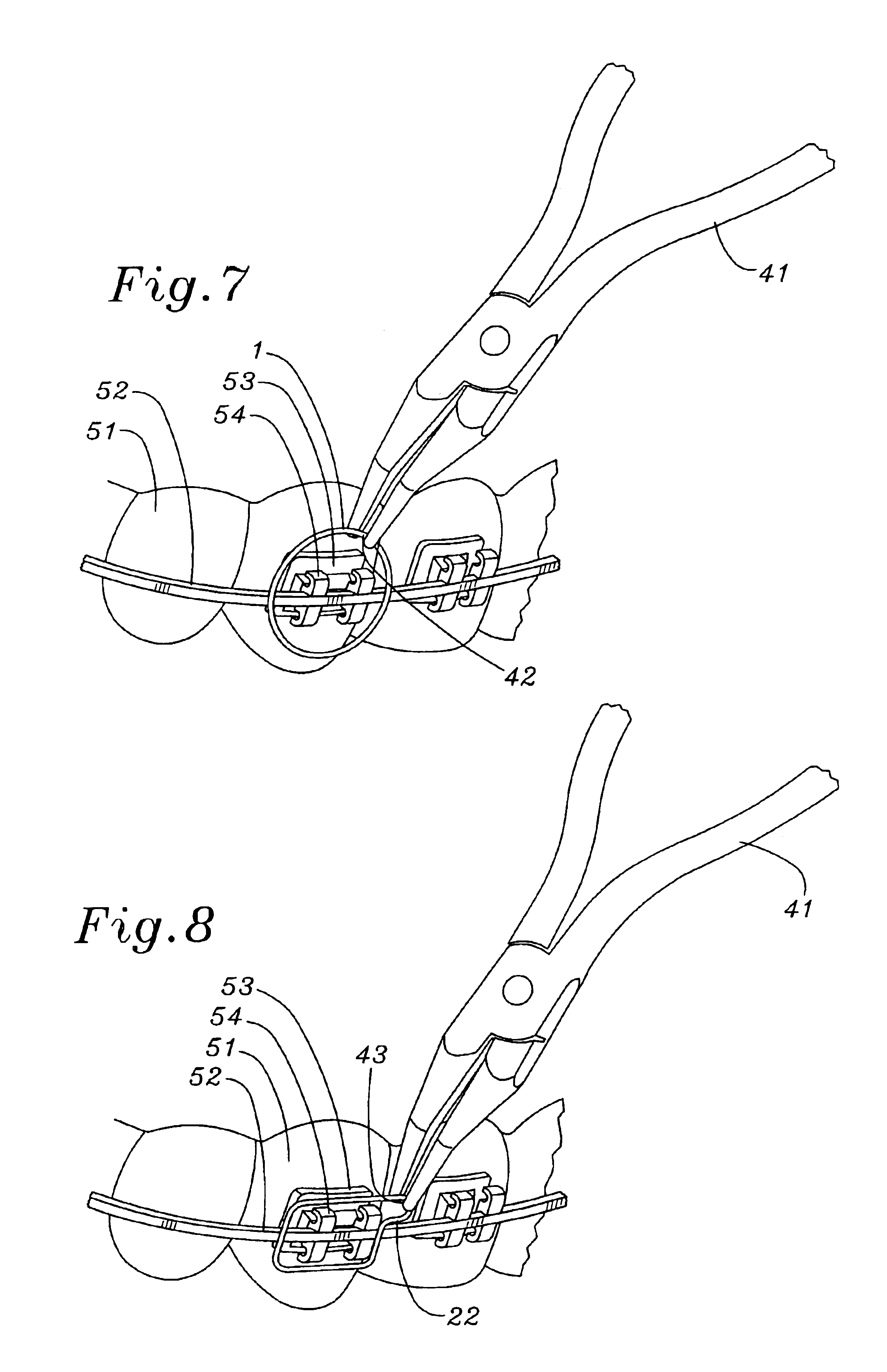
[0026]Referring to FIGS. 1-3, the orthodontic hook 1 is constructed for installation on a conventional orthodontic assembly of an arch wire 52 attached to brackets 53 which are attached to the front faces of teeth 51, as shown FIGS. 7-10. Each tooth bracket 53 includes a base 55 bonded to the outer surface of a tooth 51. A body projects outwards from the bracket base 55 and carries a plurality of wings 54 projecting upwards and downwards from the opposite side of a groove or slot 56 between them in which the arch wire 52 is fitted. Normally the arch wire 52 is tied to each bracket 53 by an elastomeric ring or a fine wire as shown in FIGS. 7, 8, and 10. In FIGS. 7, 9, and 10 the orthodontic hook 1 is tied to the bracket tie wings 54 either under the arch wire 52 or over the arch wire 52, securing the arch wire 52. The orthodontic hook 1 is installed on the bracket assembly virtually any location around the dental arch.

[0027]The orthodontic hook 1 may be made from various types of all...


PUM


Abstract

An attachable orthodontic hook for use on an orthodontic appliance wherein the hook is formed from a continuous wire which forms a twisted hook when it is attached to an orthodontic appliance. When installed there is only one end. The cut pigtail has been eliminated.

Description

FIELD OF THE INVENTION[0001]This invention relates, in general, to an improved orthodontic device, and more particularly to an orthodontic assembly which is attached to an orthodontic bracket, forming an orthodontic hook. More particularly, the orthodontic assembly is constructed from a continuous wire and attached to an orthodontic bracket in a manner that a pigtail hook projects from the orthodontic bracket.BACKGROUND OF THE INVENTION[0002]The orthodontic procedures for straightening teeth today involves the placement of brackets on the external of the teeth with an adhesive and connecting a force, an arch wire, to the brackets to move the teeth. Hooks have been secured to the brackets and arch wires for use as an anchoring device for intramaxillary or intermaxillary springs, elastomeric modules, elastics, or ligature wires. In the treatment of dentofacial deformities where orthognathic surgery has moved one or both jaws the jaws are often postoperatively ligated together using in...

Claims


Application Information

Patent Timeline
Patent Type & Authority Patents(United States)
IPC IPC(8): A61C7/02A61C7/00
CPCA61C7/026A61C7/02
Inventor BLOORE, JOHN A.BLOORE, GLENN E.
Owner BLOORE JOHN A
Learn More