
Scintillator panel and radiation image sensor

a radiation image sensor and scintillator technology, applied in instruments, optical radiation measurement, fluorescence/phosphorescence, etc., can solve the problems of radiation detectors and insufficient optical output, and achieve the effect of enhancing the optical output of scintillator panels and enhancing the output of radiation image sensors

Inactive Publication Date: 2005-06-28
HAMAMATSU PHOTONICS KK
View PDF56 Cites 1 Cited by
  • Summary
  • Abstract
  • Description
  • Claims
  • Application Information

AI Technical Summary

Benefits of technology

[0008]It is an object of the present invention to provide a scintillator panel having an enhanced optical output, and a radiation image sensor using a scintillator panel having an enhanced optical output.
[0010]Since the light-transmitting thin film having a refractive index lower than that of the scintillator is disposed between the substrate and the scintillator in this scintillator panel, the light generated from the scintillator can be reflected by the light-transmitting thin film to the optical output side, whereby the optical output of scintillator panel can be enhanced.
[0012]In this radiation image sensor, since the light-transmitting thin film having a refractive index lower than that of the scintillator is disposed between the substrate and the scintillator in the scintillator panel, the optical output of scintillator panel increases. As a consequence, the output of radiation image sensor can be enhanced.

Problems solved by technology

Meanwhile, though it is necessary for the scintillator panel to have a sufficiently high optical output in order to attain clear images in a radiation detector, the optical output has not been sufficient in the above-mentioned radiation detector.

Method used


Image

  • Scintillator panel and radiation image sensor
  • Scintillator panel and radiation image sensor
  • Scintillator panel and radiation image sensor

Examples


Embodiment Construction

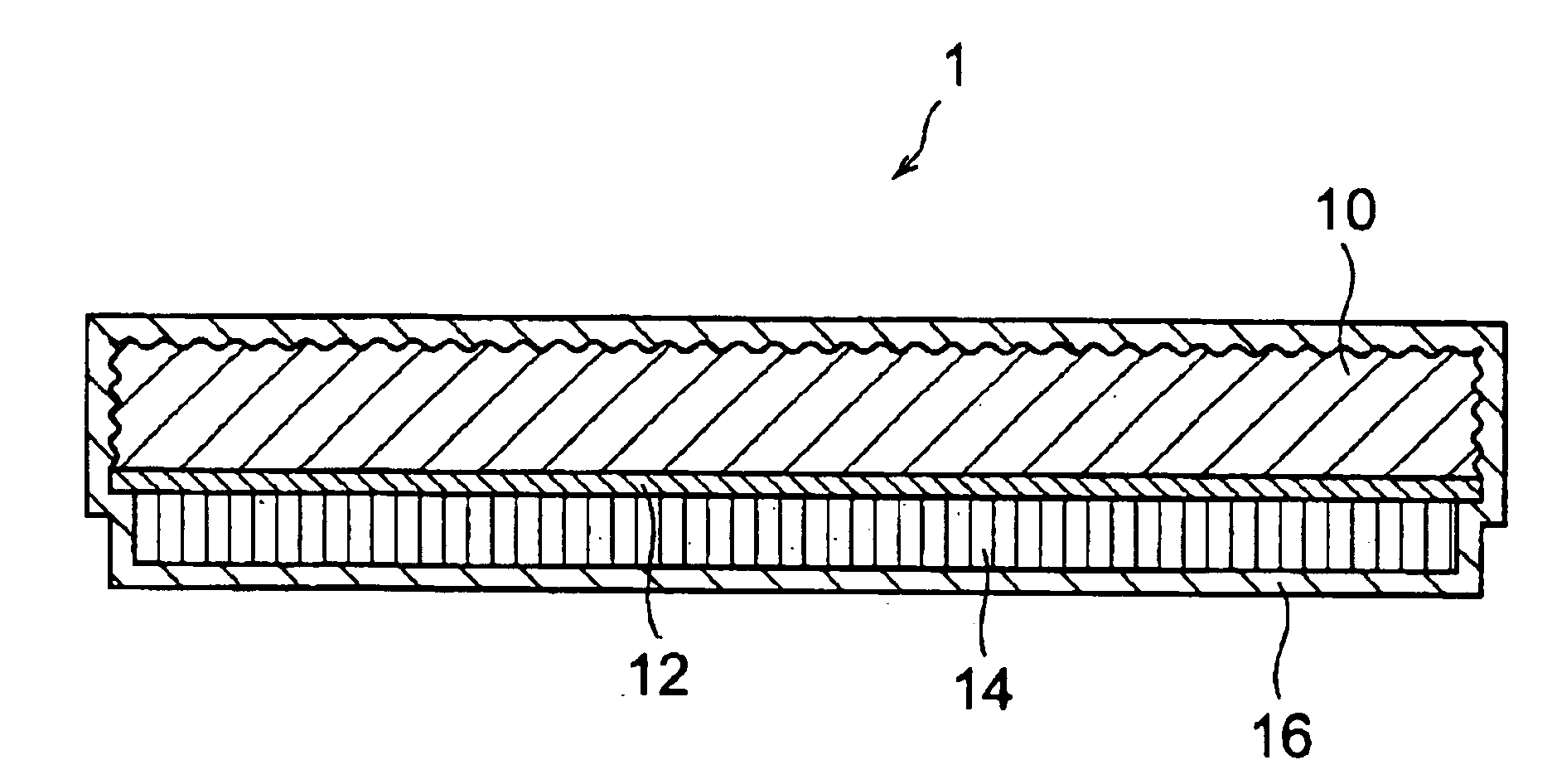
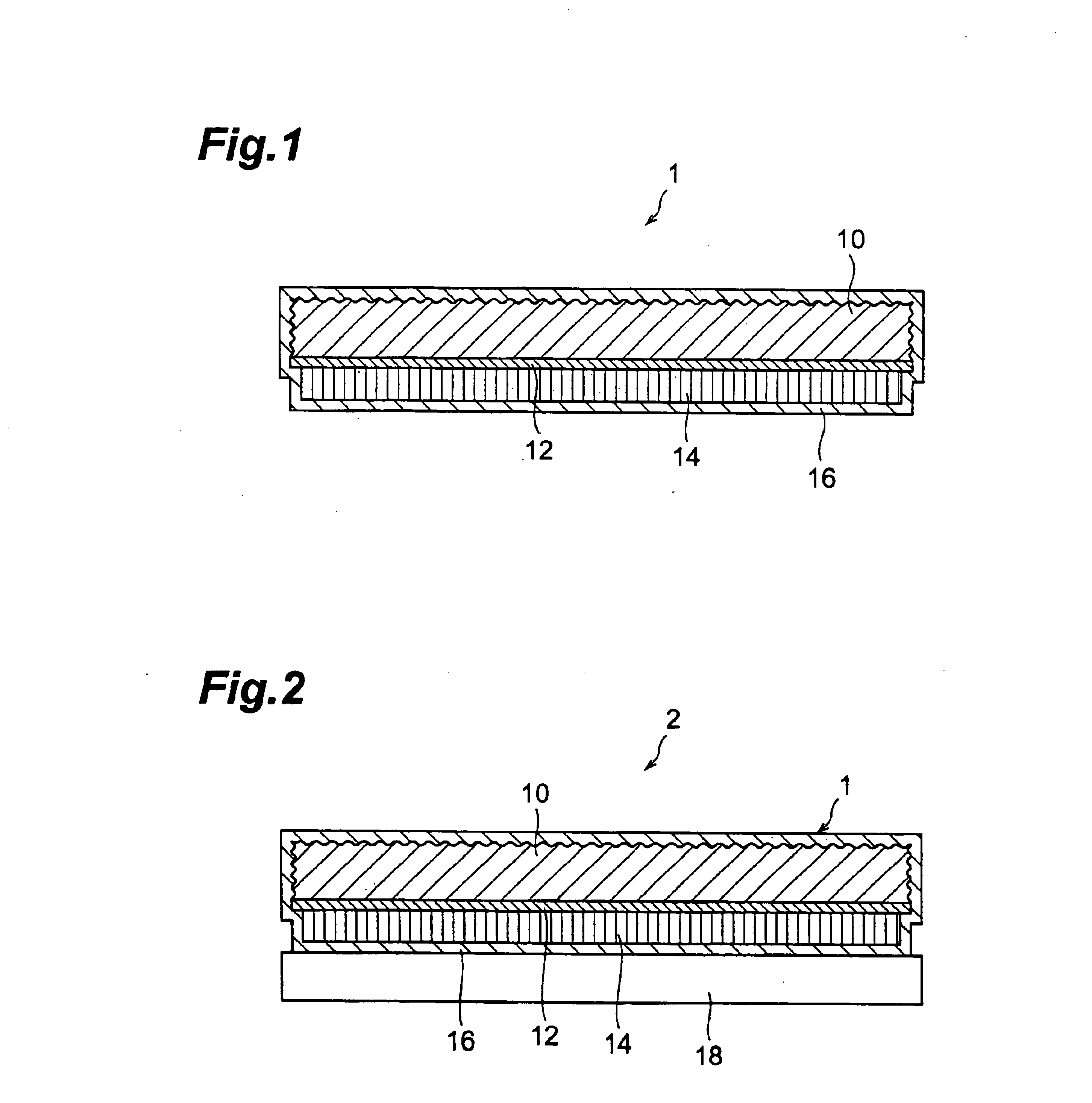
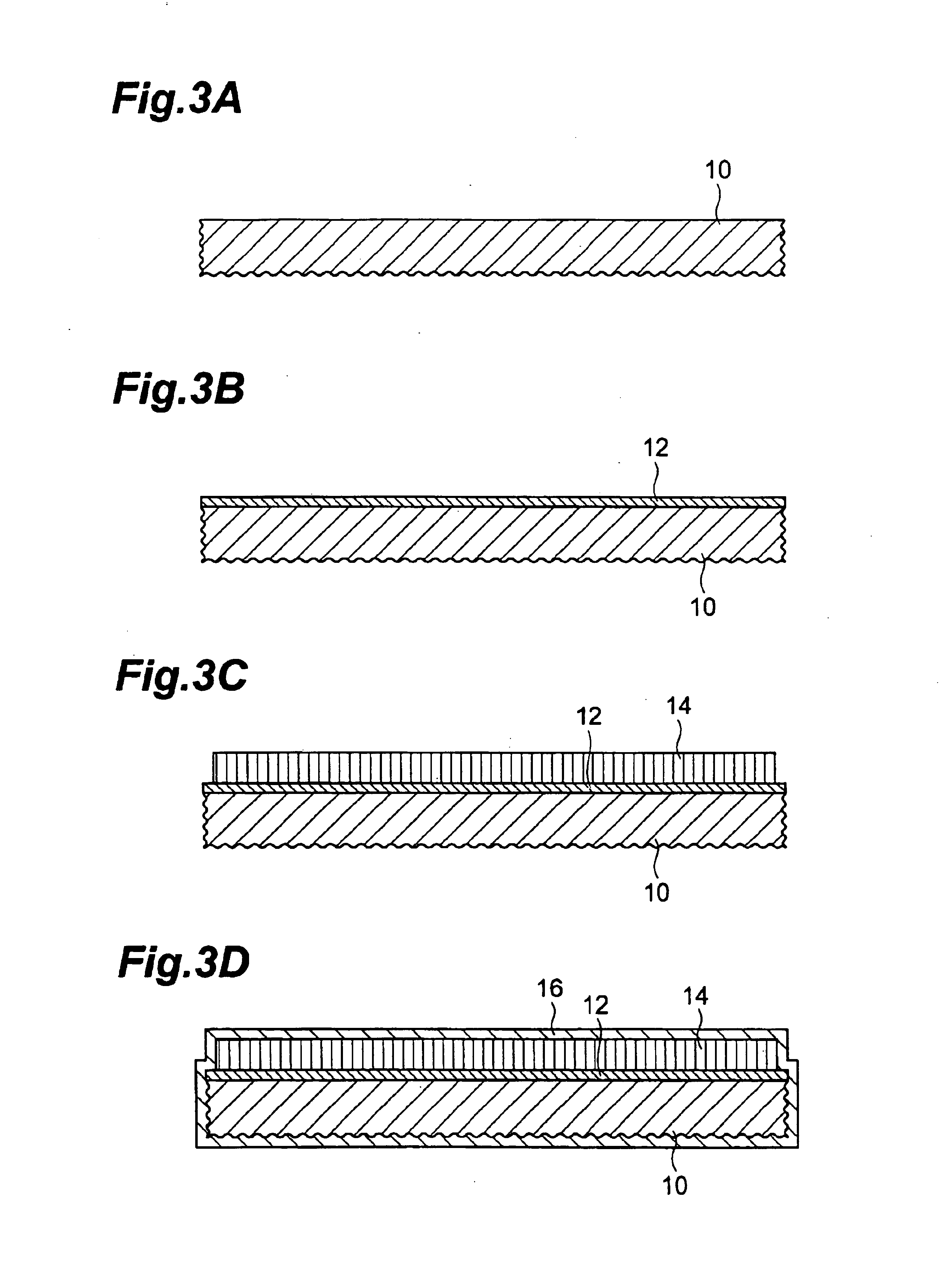
[0023]In the following, a first embodiment of the present invention will be explained with reference to FIGS. 1, 2, and 3A to 3D. FIG. 1 is a sectional view of a scintillator panel 1, whereas FIG. 2 is a sectional view of a radiation image sensor 2.

[0024]As shown in FIG. 1, one surface and side faces of a substrate 10 made of Al in the scintillator panel 1 are sandblasted, whereas the other surface is processed into a mirror surface. Also, the other surface is formed with an MgF2 film (refractive index=1.38) 12 as a low refractive index material (material having a refractive index lower than that of a scintillator 14). The surface of this MgF2 film 12 is formed with the scintillator 14 having a columnar structure for converting incident radiation into visible light. Here, Tl-doped CsI (refractive index=1.8) is used for the scintillator 14. Together with the substrate 10, the scintillator 14 is covered with a polyparaxylylene film 16.

[0025]As shown in FIG. 2, on the other hand, the r...


PUM


Abstract

A surface of a substrate made of Al in a scintillator panel 1 is sandblasted, whereas one surface thereof is formed with an MgF2 film as a low refractive index material. The surface of MgF2 film is formed with a scintillator having a columnar structure for converting incident radiation into visible light. Together with the substrate, the scintillator is covered with a polyparaxylylene film.

Description

RELATED APPLICATIONS[0001]This is a Continuation application of U.S. patent application Ser. No. 09 / 971,644 filed on 9 Oct. 2001 now U.S. Pat. No. 6,753,531 which is a Continuation-In-Part application of International Patent Application No. PCT / JP99 / 01912 filed on 9 Apr. 1999.BACKGROUND OF THE INVENTION[0002]1. Field of the Invention[0003]The present invention relates to a scintillator panel and a radiation image sensor which are used in medical X-ray photography and the like.[0004]2. Related Background Art[0005]While X-ray sensitive films have conventionally been used in medical and industrial X-ray photography, radiation imaging systems using radiation detectors have been coming into widespread use from the viewpoint of convenience and storability of photographed results. In such a radiation imaging system, pixel data caused by two-dimensional radiation are acquired as an electric signal by a radiation detector, and this signal is processed by a processing unit, so as to be displa...

Claims


Application Information

Patent Timeline
Patent Type & Authority Patents(United States)
IPC IPC(8): G01T1/20G01T1/00
CPCG01T1/2002G01N23/083
Inventor HOMME, TAKUYATAKABAYASHI, TOSHIO
Owner HAMAMATSU PHOTONICS KK
Learn More