
Method and apparatus for estimating delay and jitter between many network routers using measurements between a preferred set of routers

a network router and router technology, applied in the field of computer networks, can solve problems such as jitter, delay deviation, and current monitoring methods not as useful as might be desired, and achieve the effect of not being able to scale well in large networks, and measuring schemes are not easy to implemen

Inactive Publication Date: 2005-06-28
CISCO TECH INC
View PDF21 Cites 30 Cited by
  • Summary
  • Abstract
  • Description
  • Claims
  • Application Information

AI Technical Summary

Benefits of technology

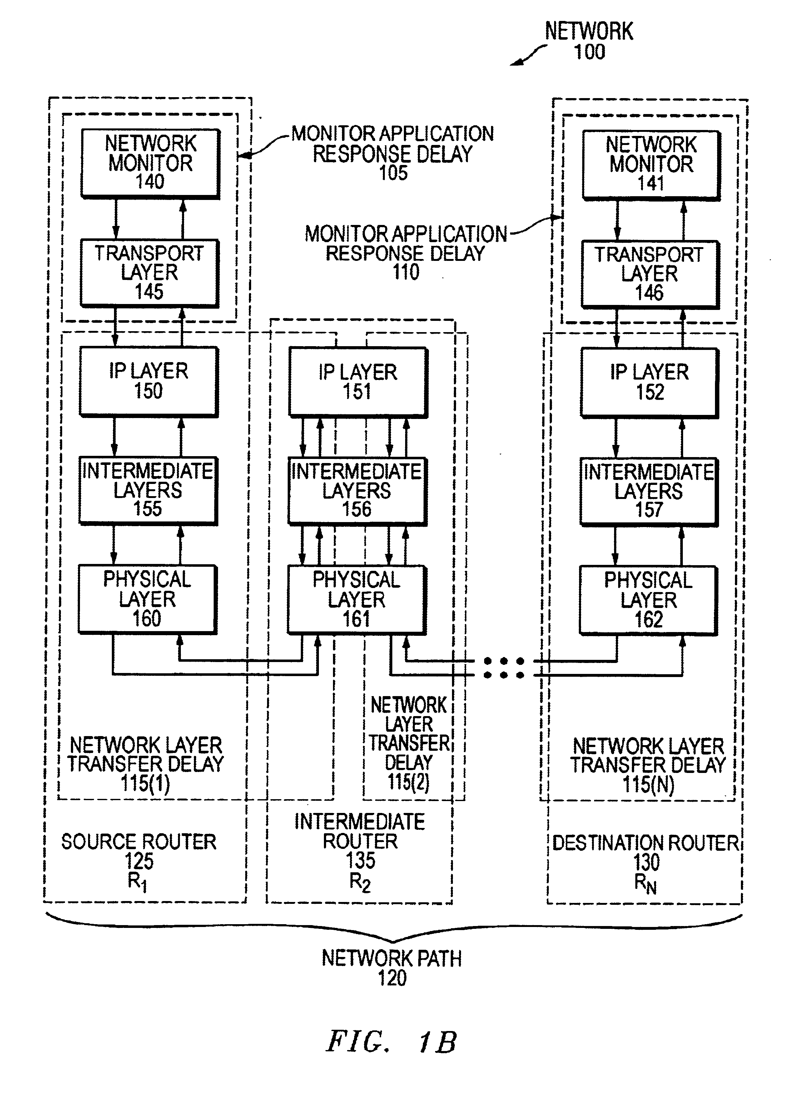
[0011]The present invention, in various embodiments, addresses the aforementioned problems by providing techniques for measuring network performance metrics, such as delay encountered between nodes in a network, and delay-jitter (jitter) observed therein. Advantageously, embodiments of the present invention allow such measurements to be made between preferred nodes of the network, without generating excessive network traffic, and are capable of accounting for delays both between nodes (the delay over inter-node links) and within nodes. Also advantageously, embodiments of the present invention are less demanding from a measurement perspective, being on the order of N+M (O(N+M)).
[0013]The techniques described herein provide several advantages. Such techniques permit a network operator some measure of control over the network elements and network links involved in the measurements taken by such a procedure, allowing the operator to minimize the number of network elements involved, traffic over congested links and so on. These techniques also address the fundamental concern of a measurement scheme's scalability in monitoring delay and jitter in increasingly large networks, with known or partly known topology and routing. The techniques result in a significant reduction in traffic overhead due to exchange of probe packets when compared to existing techniques. The savings can be especially significant in networks having a large requirements set. Further, in a network employing TCP / IP protocols, the methods described herein separately accounts for IP-level transfer delay over a link and the delay in processing probe packets within a router (i.e., the delay experienced in generating and / or receiving such packets), thereby helping to isolate and identify links that are over or under provisioned. Simplicity and ease of implementation are also attractive features of a technique according to the present invention.

Problems solved by technology

Another is the jitter, or deviation in delay, experienced by such data packets.
Unfortunately, current methods of monitoring are not as useful as might be desired.
As can be seen from the complexity of the technique (O(N2)), this measurement scheme does not scale well in large networks as the number of specified pairs of routers to be monitored increases dramatically.
In such cases, the resulting network traffic due to probe packets can be large and, therefore, unsustainable as a result of the bandwidth consumed thereby.
This problem of scalability may be further compounded by the fact that networks being deployed are diff-serv (DS) enabled.

Method used


Image

  • Method and apparatus for estimating delay and jitter between many network routers using measurements between a preferred set of routers
  • Method and apparatus for estimating delay and jitter between many network routers using measurements between a preferred set of routers
  • Method and apparatus for estimating delay and jitter between many network routers using measurements between a preferred set of routers

Examples


Embodiment Construction

[0025]The following is intended to provide a detailed description of an example of the invention and should not be taken to be limiting of the invention itself. Rather, any number of variations may fall within the scope of the invention which is defined in the claims following the description.

Introduction

[0026]Embodiments of the measurement techniques described herein address the central issue of scalability. These methods allow (a) network performance metrics, such as delay and jitter, to be measured between a significantly smaller subset of pairs of routers, and (b) the corresponding metrics for the remaining specified pairs of routers to be computed based on these measurements. These methods include (a) the identification of network paths for which measurements must be undertaken, and (b) the computation of the metrics for the remaining specified pairs of routers for which measurements are not taken. Advantageously, the present invention allows control over which routers and link...


PUM


Abstract

A method and apparatus for determining a network performance metric in a network is described. The network includes a number of network elements and a number of links. Each of the network elements is coupled to at least one other of the network elements by at least one of the links. The method includes forming a first set of network element pairs, ordering a first number of network element pairs, forming a second set of network element pairs, measuring a measured network performance metric between a first network element pair and computing a computed network performance metric.

Description

CROSS-REFERENCES TO RELATED APPLICATIONS[0001]This application is related to patent application Ser. No. 09 / 583,177 entitled “METHOD AND APPARATUS FOR ESTIMATING DELAY AND JITTER BETWEEN NETWORK ROUTERS,” having B. N. Jain and K. McCloghrie as inventors. This application is assigned to Cisco Technology, Inc., the assignee of the present invention, and is hereby incorporated by reference herein.BACKGROUND OF THE INVENTION[0002]1. Field of the Invention[0003]The present invention relates to computer networks, and, more particularly, to a method and apparatus for estimating a network performance metric, such as delay and delay-jitter (jitter), between a collection of pairs of network elements (e.g., routers) in a network.[0004]2. Description of the Related Art[0005]As computer networks grow, in terms of the number of network elements (e.g., routers) contained therein, the measurement of network performance metrics becomes of increasing importance. By measuring such metrics, network par...

Claims


Application Information

Patent Timeline
Patent Type & Authority Patents(United States)
IPC IPC(8): G01R31/08H04L12/28H04L12/26
CPCH04L43/087H04L43/0858
Inventor JAIN, BIJENDRA N.MCCLOGHRIE, KEITH
Owner CISCO TECH INC
Learn More