
Autoconfiguring IP routers

a router and auto-configuration technology, applied in the field of data communication networks, can solve the problems of time-consuming and error-prone configuration process, undesirable drawbacks of manual configuring of network addresses, etc., and achieve the effect of avoiding the drawbacks of a centralized approach

Inactive Publication Date: 2005-06-28
ORACLE INT CORP
View PDF6 Cites 23 Cited by
  • Summary
  • Abstract
  • Description
  • Claims
  • Application Information

AI Technical Summary

Benefits of technology

[0010]In accordance with the present invention, methods and apparatus for automatically configuring nodes in a network region with network-layer addresses are disclosed. In particular, one disclosed technique operates in a fully distributed manner, and thus avoids the drawbacks of a centralized approach.
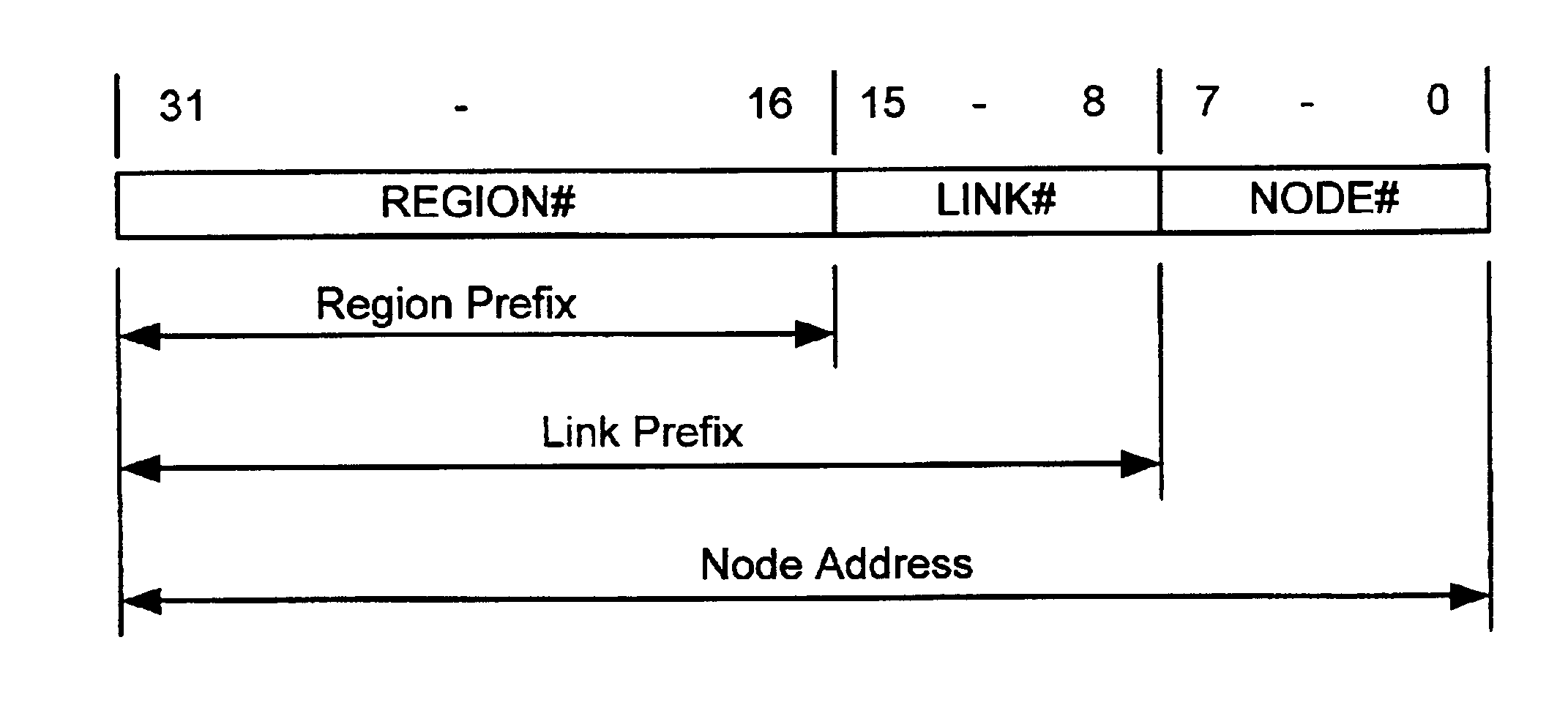
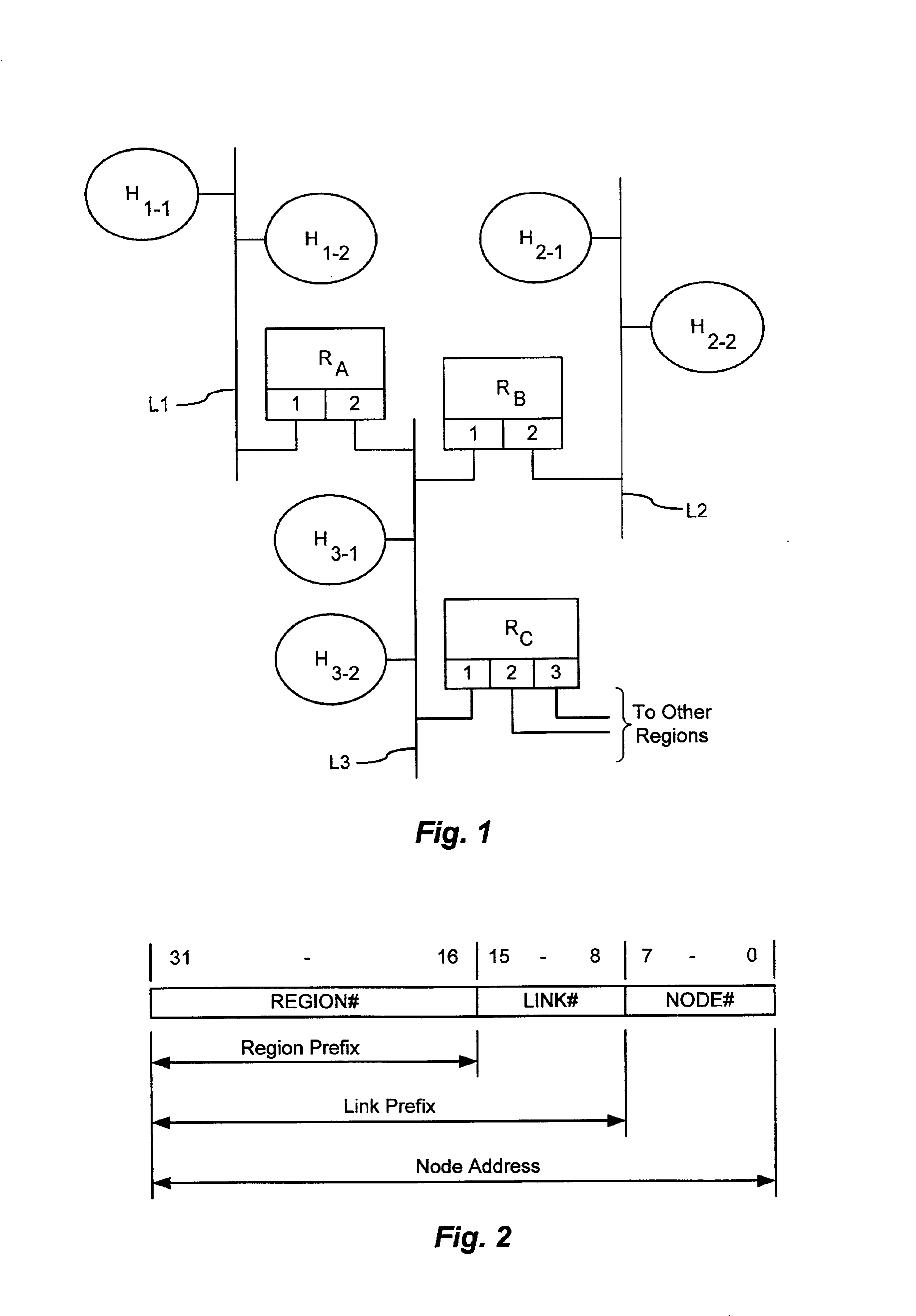
[0015]The above method achieves auto-configuration of unique network-layer addresses throughout the network region in a fully distributed fashion. Also, the segmentation of the addresses into distinct fields allows independent re-configuring at different levels in the network. For example, a region prefix assigned to a third field of the network-layer addresses of the nodes in the network region can be re-configure(d by a network service provider without the need to re-configure the link numbers. Likewise, the nodes on a link can be re-numbered without requiring the re-configuration of the link prefix.

Problems solved by technology

However, the manual configuring of network addresses can have undesirable drawbacks.
The configuration process can be time-consuming and error-prone.

Method used


Image

  • Autoconfiguring IP routers
  • Autoconfiguring IP routers

Examples


Embodiment Construction

[0022]An Internet Protocol (IP) network is partitioned into regions, each of which includes host computers or end nodes, routers, and links. Each link interconnects a subset of the nodes of the region. The links are interconnected by the routers. A simplified example of such an IP network region is shown in FIG. 1, and is described below.

[0023]For ease of description, in the illustrated case it is assumed that each link in the region is an Ethernet Local Area Network (LAN), and that each node has a unique 48-bit “media access control” (MAC) address. Uniqueness of Ethernet MAC addresses is guaranteed by a known administrative address-assigning process, which employs a single address-assigning authority. As described below, the disclosed methods rely on the ability to uniquely identify routers in a network region. This criterion can be met conveniently by using the MAC addresses in an Ethernet-only environment. In other environments, other methods may be used to uniquely identify the ...


PUM


Abstract

In automatically configuring network-layer addresses for network nodes in a network region, a specified router on each link generates link number request messages for the link. An address-assigning node assigns a region-wise unique link number to each link identified in a request message, and returns link number assignment messages containing the assigned link numbers. Each specified router assigns the link number from a received link number assignment message to a field of the network-layer addresses of the nodes on the associated link. According to a variation of the method, each specified router self-selects a link number and communicates with the other specified routers to avoid conflicts. Each specified router receives messages from the other specified routers containing numbers selected as region-wise unique link numbers for other links. Each specified router stores the received link numbers in association with the respective links in a local database. To configure a link number for the local link, a specified router selects a candidate region-wise unique link number not already associated with another link in the local database, generates a message containing the selected number, and propagates the message within the network region. Each specified router monitors the messages to detect when another specified router has selected the same link number. When this occurs, the specified router evaluates a conflict-resolution criterion to determine which router is entitled to keep a duplicate link number, and selects a new link number if necessary.

Description

CROSS REFERENCE TO RELATED APPLICATIONS[0001]Not ApplicableSTATEMENT REGARDING FEDERALLY SPONSORED RESEARCH OR DEVELOPMENT[0002]Not ApplicableBACKGROUND OF THE INVENTION[0003]The present invention is related to the field of data communications networks, and more particularly to techniques for configuring node addresses in Internet Protocol (IP) and other networks.[0004]One task to be performed in managing data communications networks is assigning addresses to network nodes, a process also referred to as “configuring” addresses in the network. In particular, it is necessary to configure addresses used at the network layer, or layer 3, of network operation as described by the Open Systems Interconnect (OSI) communications model. At the network layer, message routing protocols are generally used to route messages among the network nodes. Network-layer addresses are used to uniquely identify the sources and destinations of messages, and devices known as, “routers” use these addresses to...

Claims


Application Information

Patent Timeline
IPC IPC(8): H04L12/56H04L29/12
CPCH04L29/12009H04L29/12207H04L29/12801H04L61/6004H04L45/44H04L61/20H04L45/02H04L61/00H04L61/50H04L2101/604H04L45/03
Inventor PERLMAN, RADIA J.GUTTMAN, ERIC A.
Owner ORACLE INT CORP
Learn More