
Speaker unit for low frequency reproduction

a low frequency reproduction and speaker technology, applied in the direction of transducer details, electrical transducers, instruments, etc., can solve the problems of deteriorating orientation of the sound image of the sub woofer ssub>5/sub>, requiring a corresponding large size, etc., to achieve the effect of reducing distortion and low frequency

Inactive Publication Date: 2005-06-28
ALPINE ELECTRONICS INC
View PDF7 Cites 14 Cited by
  • Summary
  • Abstract
  • Description
  • Claims
  • Application Information

AI Technical Summary

Benefits of technology

[0011]It is an object of the present invention to provide a speaker unit for low frequency reproduction wherein distortion is reduced and the orientation of a sound image of the lower side frequency region is augmented.
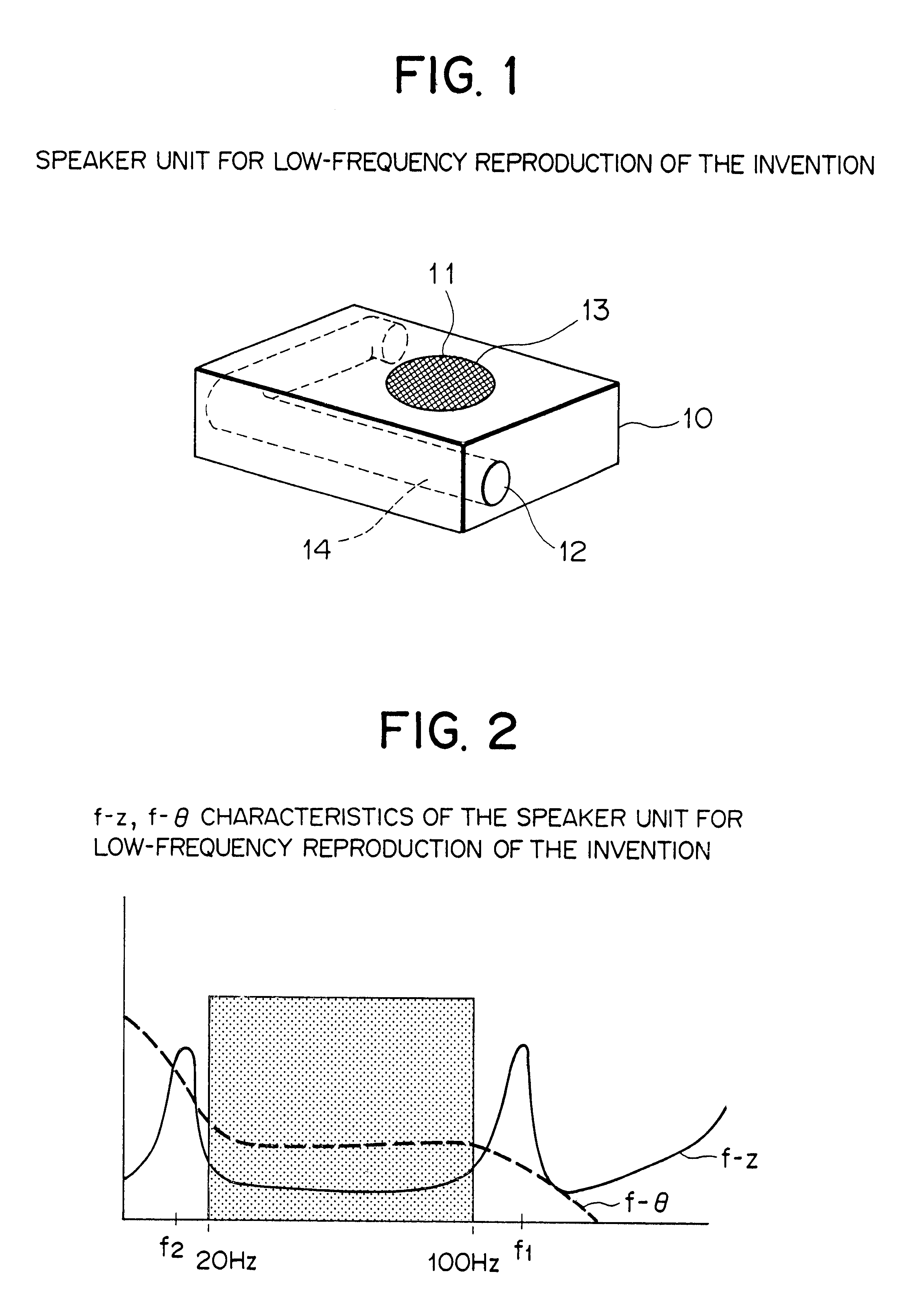
[0016]With the speaker unit for low frequency reproduction, since the first and second resonance frequencies of the speaker unit are set outside the actually used frequency band, the phase characteristic of the speaker unit within the actually used frequency band can be made substantially flat, and consequently, a phase delay and a time delay are eliminated. As a result, the distortion and so forth which are caused by a phase displacement from some other speaker unit concurrently used are reduced, and a time delay for each frequency is eliminated. Consequently, the orientation of a sound image in a low frequency region is augmented significantly and a clear orientation feeling can be obtained.
[0018]Furthermore, with the speaker unit for low frequency reproduction, since a speaker unit having a low compliance (having a small amplitude) can be used in order to implement the speaker unit, possible damage to the speaker unit by an excessively great amplitude of output sound in the low frequency band can be eliminated, and consequently, increased reliability can be achieved.

Problems solved by technology

However, a baffle which is effective also with regard to low frequencies requires a corresponding large size and is not practical.
Further, a problem occurs that the orientation of a sound image of the sub woofer S5 is deteriorated.

Method used


Image

  • Speaker unit for low frequency reproduction
  • Speaker unit for low frequency reproduction
  • Speaker unit for low frequency reproduction

Examples


Embodiment Construction

A. General Construction

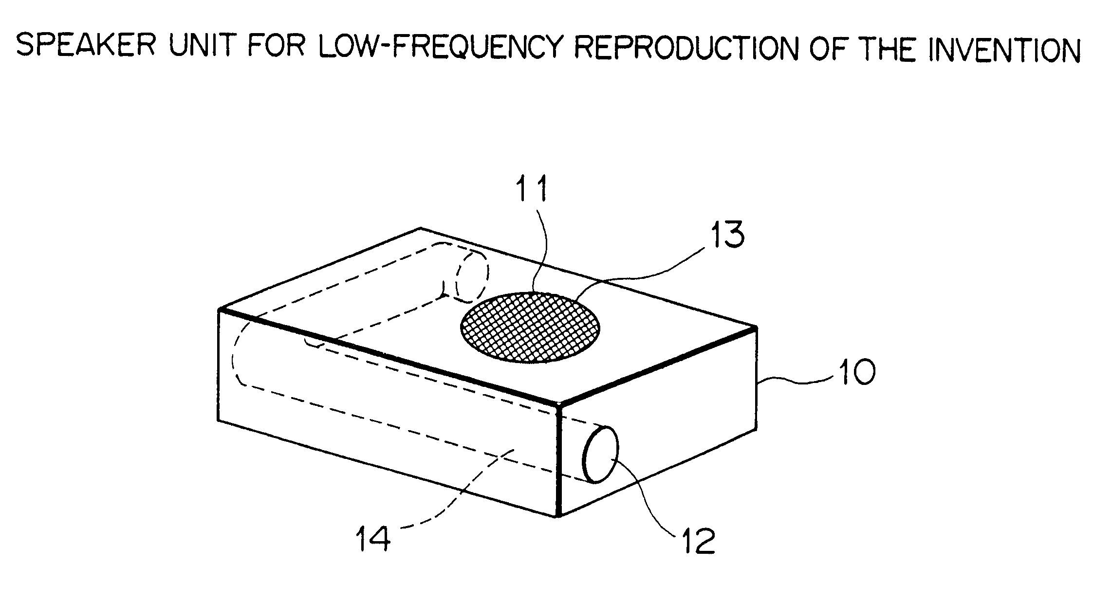
[0032]Referring to FIG. 1, there is shown a speaker unit for low frequency reproduction to which the present invention is applied. The speaker unit for low frequency reproduction includes an enclosure 10 having a speaker opening 11 and a port (opening) 12 formed in adjacent faces thereof. A speaker 13 is mounted in the inside of the enclosure 10 such that it is fitted in the speaker opening 11. Further, a duct (pipe) 14 which defines the port 12 extends substantially in an L shape in the inside of the enclosure 10.

[0033]In the speaker unit for low frequency reproduction shown in FIG. 1, the speaker 13 and the duct 14 are designed such that the resonance frequency (first resonance frequency) f1 of the speaker 13 when the speaker 13 is mounted in the enclosure 10 may be higher than a higher side frequency of an actually used frequency band (about 20 Hz to 100 Hz) and the resonance frequency (second resonance frequency) f2 of the port 12 may be lower than a lower...


PUM


Abstract

The invention provides a speaker unit for low frequency reproduction wherein distortion is reduced and the orientation of a sound image of the lower side frequency region is augmented. To that end, the phase characteristic in an actually used frequency band is made substantially flat. The speaker unit includes a speaker enclosure, a duct formed in the speaker enclosure and having a port thereon, and a speaker mounted in the speaker enclosure. The speaker is formed such that it has a first resonance frequency set higher than a higher side frequency of the actually used frequency band (about 20 Hz to 100 Hz), while the port is formed such that it has a second resonance frequency set lower than a lower side frequency of the used frequency band. For example, the speaker includes a vibrating system having a reduced mass or a reduced compliance with which the first resonance frequency is set higher than the higher side frequency of the actually used frequency band, and the duct has an increased length or a controlled cross sectional area with which the second resonance frequency is set lower than the lower side frequency of the actually used frequency band.

Description

BACKGROUND OF THE INVENTION[0001]1. Field of the Invention[0002]This invention relates to a speaker unit for low frequency reproduction, and more particularly to a speaker unit for low frequency reproduction wherein a duct having a port (opening) formed thereon is provided in a speaker enclosure.[0003]2. Description of the Related Art[0004]Various speaker units for low frequency reproduction are conventionally known and include a speaker unit for low frequency reproduction of the phase inversion type as shown in a sectional view and a front elevational view in FIGS. 8(a) and (b), respectively. Referring to FIGS. 8(a) and 8(b), the speaker unit for low frequency reproduction of the phase inversion type shown includes a speaker 4 provided on an enclosure 3 in the form of a box in which a speaker opening 1 is formed. A duct (pipe) 5 having a port (opening) 2 is formed on a front wall of the enclosure 3. A sound absorbing material 6 is suitably disposed in the inside of the enclosure 3....

Claims


Application Information

Patent Timeline
IPC IPC(8): H04R1/28H04R1/02H04R9/02H04R7/18H04R9/04H04R31/00
CPCH04R1/2826H04R2499/13
Inventor THORSELL, ERIKCASS, GLENNOISHI, TETSUYA
Owner ALPINE ELECTRONICS INC
Learn More