Method and apparatus for optimized CO post-combustion in low NOx combustion processes

a post-combustion process and low nox technology, applied in lighting and heating apparatus, combustion types, combustion using lumps and pulverulent fuels, etc., can solve the problems of spoiled flame level reduction, complicated fine-tuning of such post-combustion techniques, etc., and achieve the effect of increasing the residence time of combustion products

Inactive Publication Date: 2005-07-05
AIR LIQUIDE AMERICA INC
View PDF24 Cites 6 Cited by
  • Summary
  • Abstract
  • Description
  • Claims
  • Application Information

AI Technical Summary

Benefits of technology

[0019]A method for optimized post-combustion of CO and unburned hydrocarbons in combustion processes where low levels of NOx emissions are to be achieved is disclosed. The method is adaptable for use in many combustion processes, including industrial boilers, utility boilers and industrial furnaces. Through the proposed technique of post-combustion, CO emissions can be kept below regulated levels without regenerating additional NOx emissions. This post-combustion method is based on a combination of a recirculation zone of the combustion products, a flue gas mixing zone and finally, an oxidant injection zone, all designed to optimize the residence time, temperature range and mixing of the various reactants. In one preferred embodiment, this method and apparatus are associated with the technology of oscillating combustion, thus providing at the same time very low NOx emissions and CO emissions, in compliance with current regulations.
[0022]Yet another object of the present invention to provide a method that sufficiently increases the residence time of combustion products inside the combustion chamber, especially in regions where temperature is low enough to prevent the formation of NOx.
[0023]Still another object of the present invention to provide enhanced mixing of combustion products inside the combustion chamber in order to favor the completion of the combustion.

Problems solved by technology

Tests have shown that the fine-tuning of such post-combustion techniques is very complicated and much of the NOx reduction achieved at flame level can be spoiled in this area if CO is not burned out in an appropriate manner.

Method used


Image

  • Method and apparatus for optimized CO post-combustion in low NOx combustion processes
  • Method and apparatus for optimized CO post-combustion in low NOx combustion processes
  • Method and apparatus for optimized CO post-combustion in low NOx combustion processes

Examples


Embodiment Construction

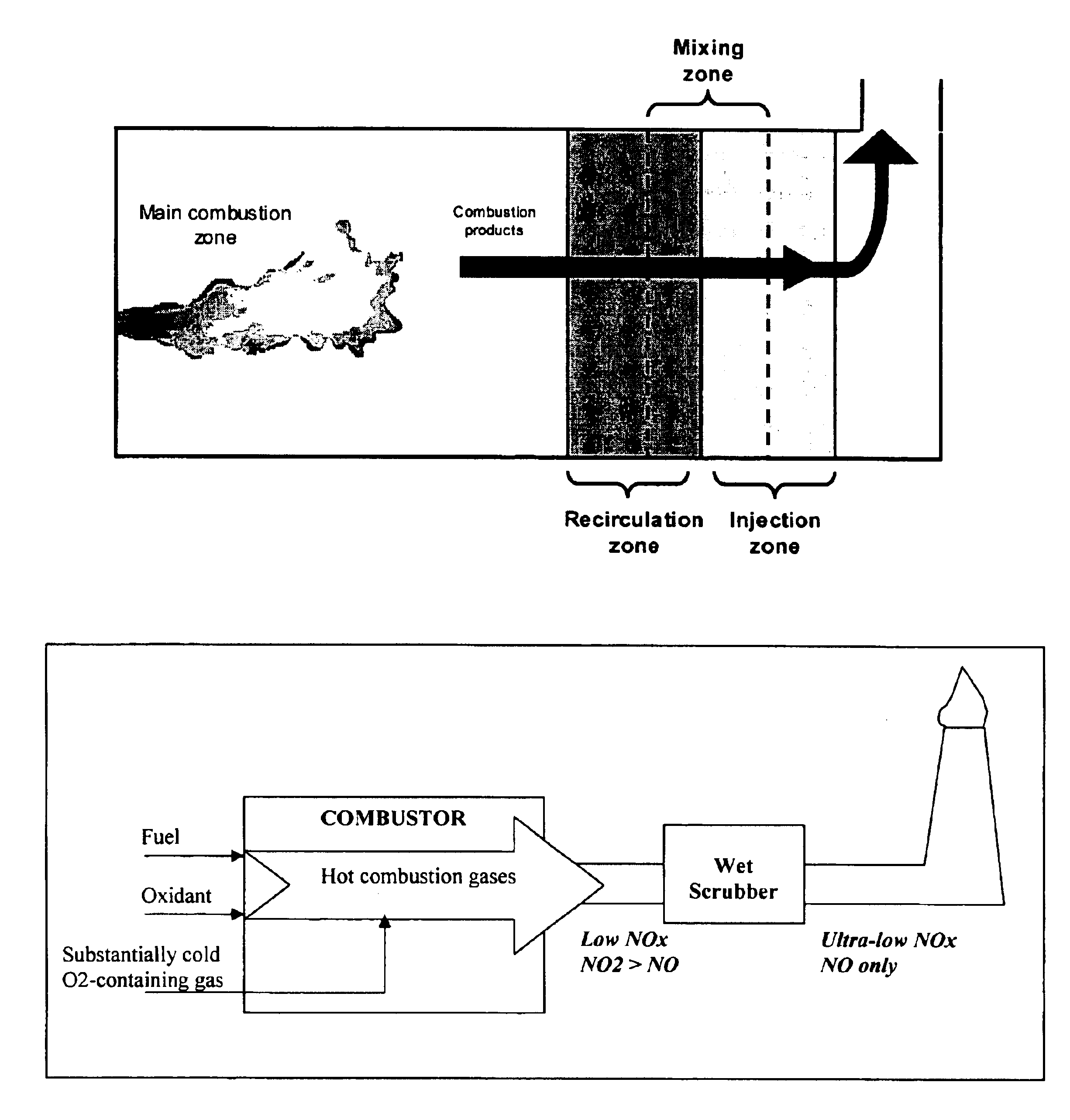
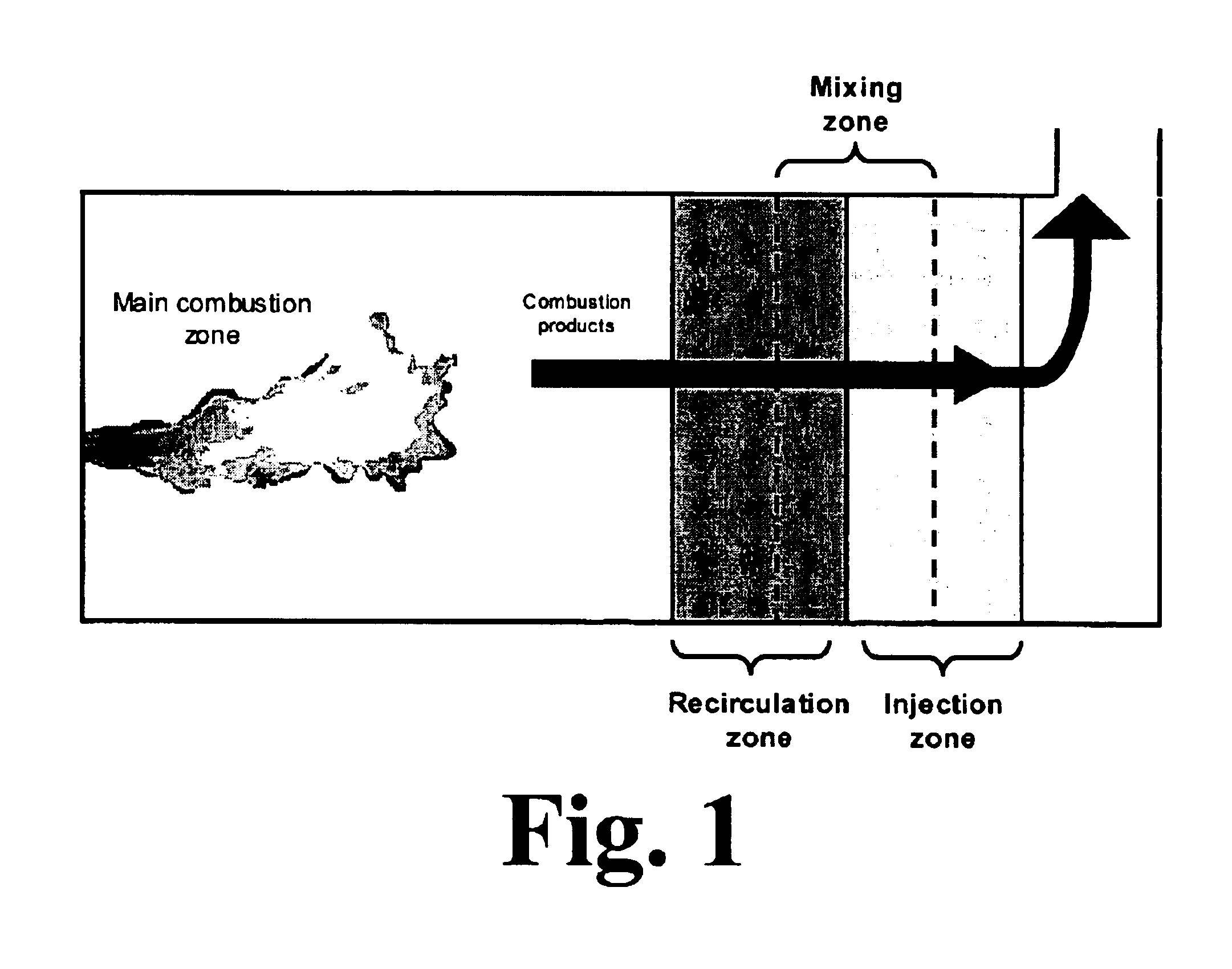
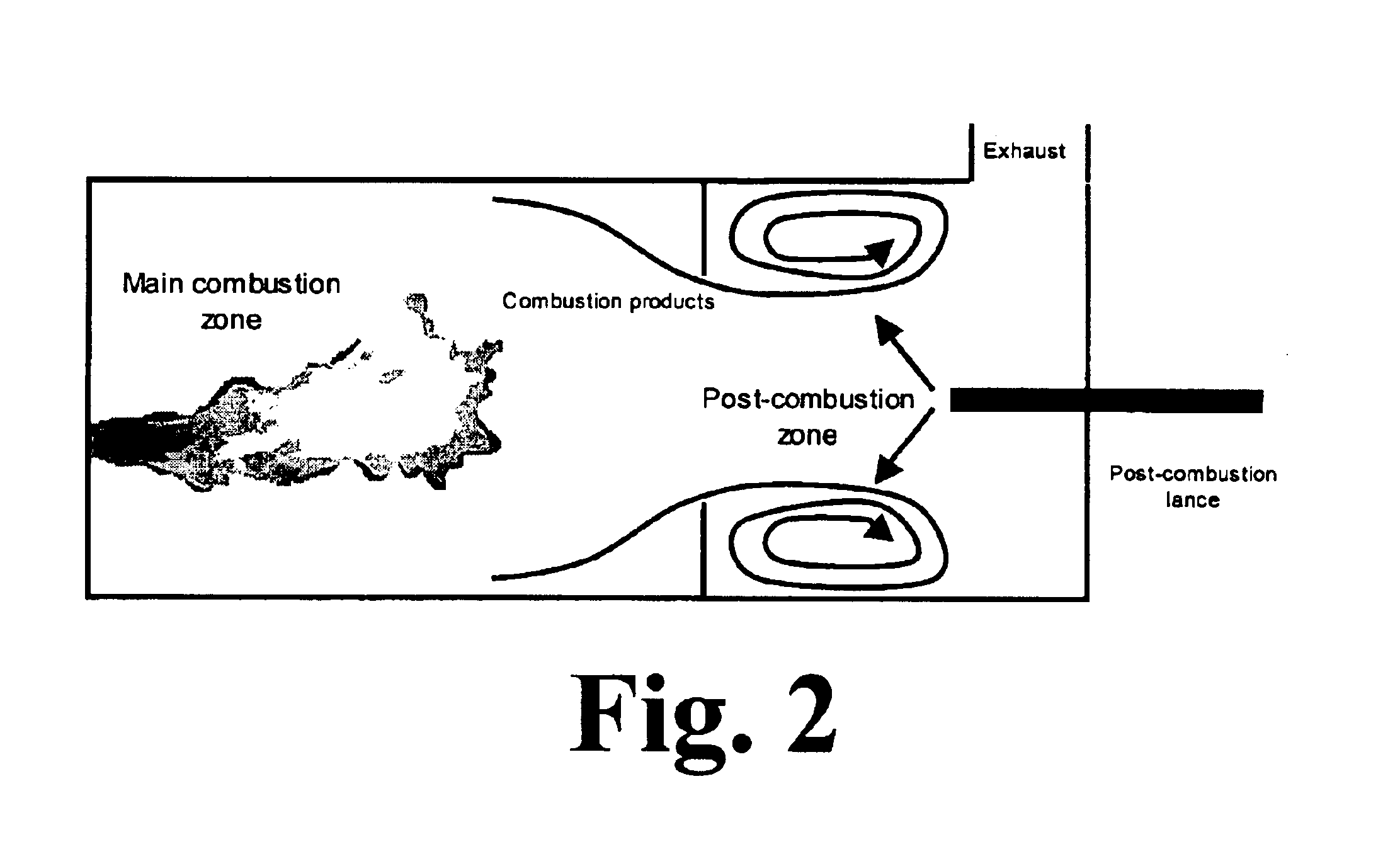
[0036]In a preferred embodiment, a method providing for optimal removal of CO in low NOx combustion process is disclosed. This method accomplishes two antagonist functions: burning out CO and unburned HC without generating additional NOx emissions. To achieve this result, three parameters are controlled. First, the residence time of the reactants in the post-combustion zone; second, the temperature at which the post-combustion is performed; and third, the completeness of mixing between the reactants.

[0037]Again referring to the preferred embodiment, a two-step method is disclosed. Since low NOx combustion techniques typically are run above stoichiometric conditions—i.e., with excess air—there is always some oxygen available in the combustion products, even if some CO and unburned HC are present. Therefore, the first step for reducing CO and unburned HC is to force the reaction between them and the still available oxygen before the exit of the combustion chamber. Then, if anything re...


PUM


Abstract

An improved process for burning a fuel to produce a flue gas is disclosed. The fuel is burned in a main combustion zone in the presence of a main combustion oxidant to produce combustion products. The combustion products are mixed in a post-combustion zone positioned downstream from the main combustion zone. The post-combustion zone is provided with a recirculation zone positioned proximate to the main combustion zone and an injection zone positioned downstream from the recirculation zone. An post-combustion oxidant is injected into the combustion products in the injection zone. At least one of (a) the residence time of the combustion products in the post-combustion zone, (b) the temperature range of the combustion products contained within the injection zone and (c) the oxygen content of the oxidant is controlled to optimize the level of CO and NOx in the flue gas.

Description

CROSS REFERENCE TO RELATED APPLICATION[0001]This application claims the benefit of U.S. Provisional Application No. 60 / 491,220, filed Jul. 30, 2003.BACKGROUND OF THE INVENTION[0002]1. Field of the Invention[0003]This invention relates to a method for optimized post-combustion of CO and unburned hydrocarbons in combustion processes where low levels of NOx emissions are to be achieved.[0004]2. Related Art[0005]High-temperature, natural gas-fired furnaces, especially those fired with preheated air, produce significant quantities of nitrogen oxides (NOx) per unit of material processed. At the same time, regulations on emissions from industrial furnaces are becoming increasingly more stringent, especially in areas such as California.[0006]Consequently, there has been a demand for improved combustion technologies allowing reduction of NOx formation. Different solutions have been developed, usually based on the principle of either staged or diluted combustion. However, the operating condit...

Claims


Application Information

Patent Timeline
Patent Type & Authority Patents(United States)
IPC IPC(8): F23C9/00F23C6/04F23C6/00F23C9/06F23M9/00F23M9/06F23L7/00
CPCF23C6/045F23C9/006F23C9/06F23L7/007F23M9/06F23K2900/05003Y02E20/322Y02E20/344Y02E20/32Y02E20/34
Inventor PENFORNIS, ERWINMARIN, OVIDIUVARAGANI, RAJANIGHANI, M. USMAN
Owner AIR LIQUIDE AMERICA INC
Why Eureka
Try Eureka