
Cylindrical burner apparatus and method

Pending Publication Date: 2022-01-13
GASTECH ENG LLC
View PDF2 Cites 0 Cited by
  • Summary
  • Abstract
  • Description
  • Claims
  • Application Information

AI Technical Summary

Benefits of technology

The present invention is a cylindrical burner system that meets the needs of industrial applications without using forced air or natural draft. It produces low NOx emissions and minimizes noise levels. The system includes an initial tube pass with discharging jets of gas fuel and a subsequent tube pass with a flue gas recirculation duct. The method of operation involves inducing a flow of combustion air and a flow of recycled flue gas, resulting in increased FGR levels and reduced NOx emissions. Overall, the cylindrical burner system is efficient, effective and provides a safer alternative for industrial applications.

Problems solved by technology

The height of the stack increases the equipment and installation costs of the system and may create space and permitting problems.
Moreover, the tall stacks required for fire tube burners commonly contribute to combustion noise problems which can be severe, and even harmful, and can prevent the natural draft systems from being used in some locations.
This phenomena, referred to as combustion “rumble,” produces low-frequency pulsations that can be so severe as to: present undesirable sound levels for workers and others, both nearby and at a distance; shake loose electrical connections and terminations, including important safety devices; loosen or break mechanical fittings and connections; and cause structural damage to property and equipment.
Unfortunately, however, forced air blower systems are more expensive to purchase, operate, and maintain, produce increased carbon dioxide in the atmosphere as blower motors consume electrical power, and may not be feasible for use in remote areas having limited or no electrical power availability.
In addition, forced air blower systems also produce significant noise levels.

Method used


Image

  • Cylindrical burner apparatus and method
  • Cylindrical burner apparatus and method
  • Cylindrical burner apparatus and method

Examples


embodiment 2

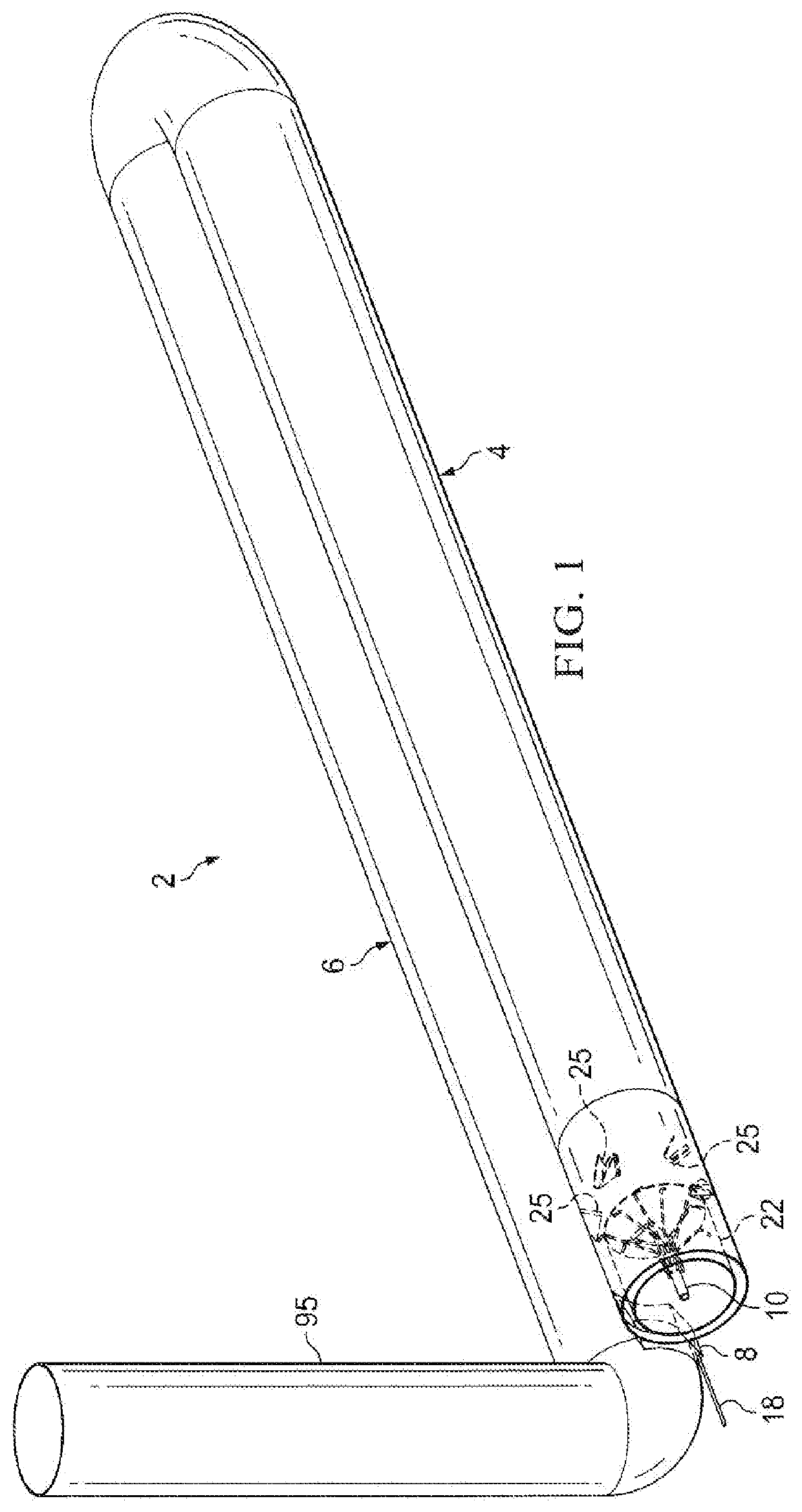
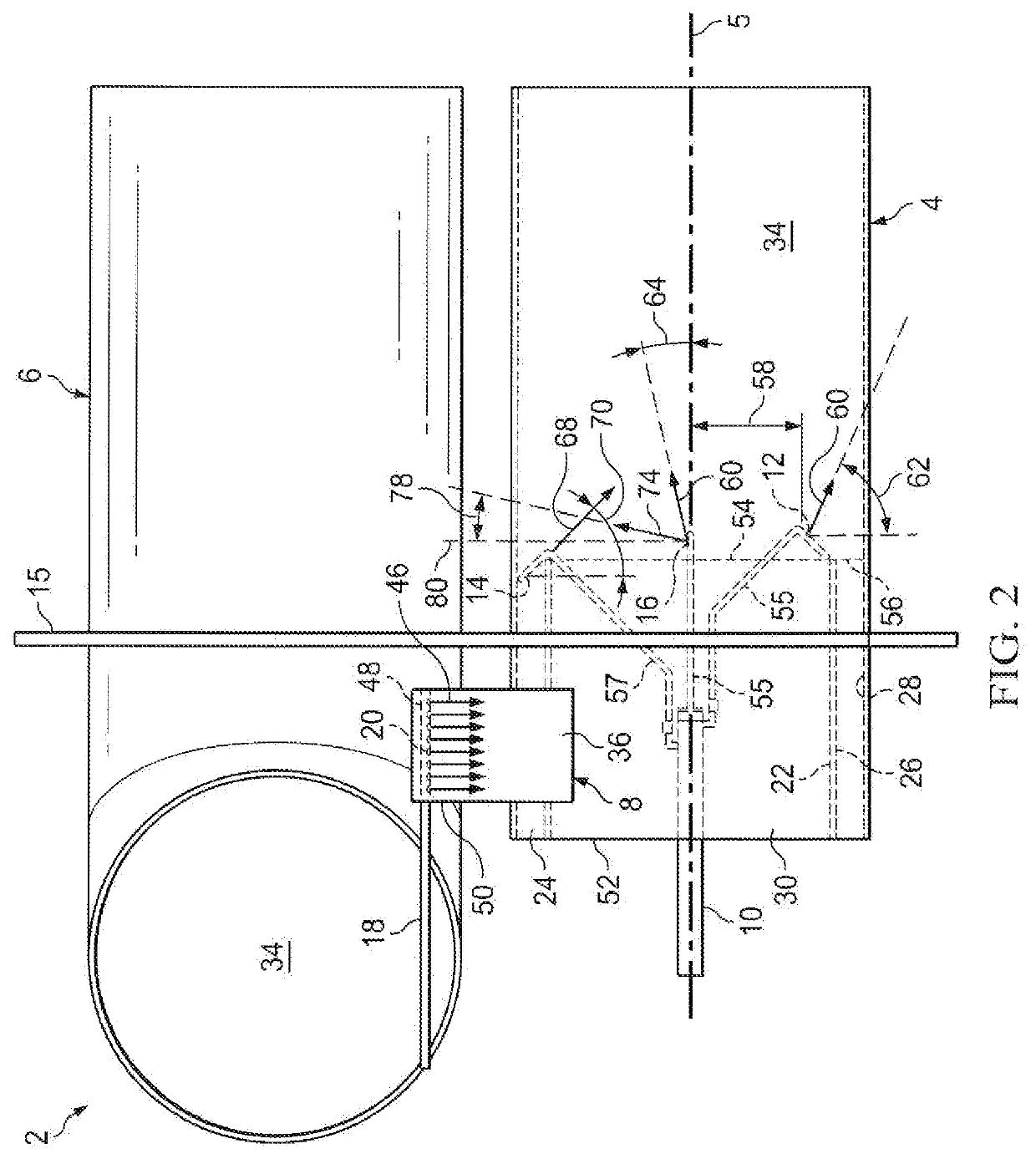
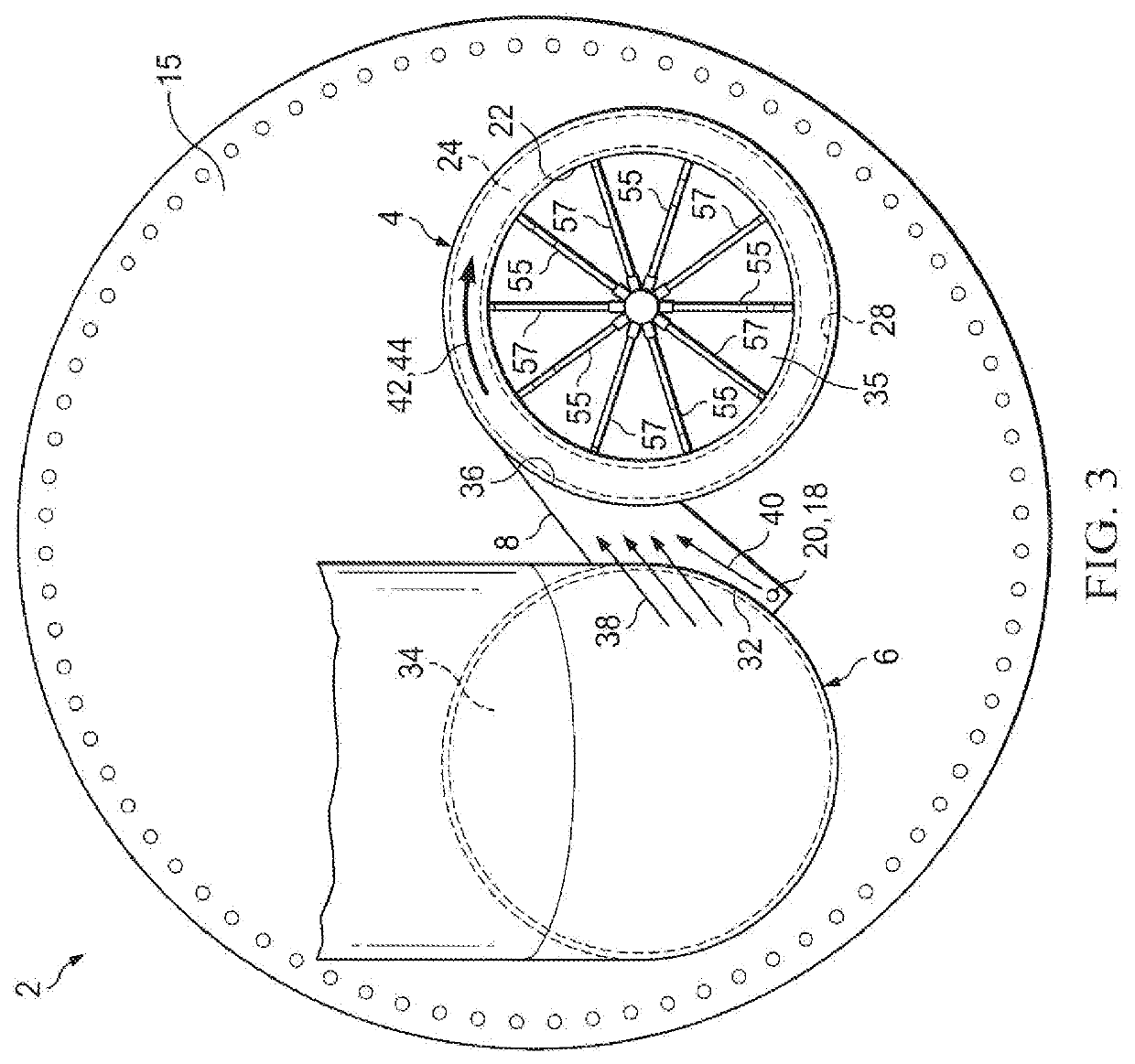
[0028]the inventive cylindrical burner apparatus is illustrated in FIGS. 1-6. The inventive apparatus 2 preferably comprises: (i) an initial burner tube pass 4 having a longitudinal axis 5; (ii) a second, third or other subsequent burner tube pass 6, downstream of the initial tube pass 4, which is preferably adjacent and parallel to the initial pass 4; (iii) a flue gas recirculation (FGR) duct 8 which extends between the subsequent tube pass 6 and the initial tube pass 4; (iv) a first fuel ejection structure or assembly, or an array of ejector elements, 10 which provides a plurality of primary fuel jet discharge ports 12, 14, and / or 16; (v) a second fuel ejection structure or assembly, or an array of ejector elements. 18 which provides one or more secondary fuel discharge ports 20; (vi) a plurality of flame stabilization structures 25 positioned in the initial tube pass 4 downstream of the primary fuel jet discharge ports 12, 14 and 16; (vii) an interior sleeve 22 positioned in the ...

embodiment 100

[0046]An alternative embodiment 100 of a fuel ejection assembly for use in the inventive cylindrical burner apparatus 2 is illustrated in FIGS. 7 and 8. The alternative fuel ejection assembly 100 replaces the first fuel ejection assembly 10 described above. The fuel ejection assembly 100 will be centrally positioned in the initial tube pass 4, forwardly of the rearward end 52 thereof, and is well suited for use with or without an interior sleeve 22, an interior annulus 24, an FGR duct 8, or a second fuel ejection structure, assembly or array 18.

[0047]The fuel ejection assembly 100 preferably comprises a central gas supply hub 102 and a plurality of, preferably 5, gas pipes or other gas conduits 104 which extend radially outward from the central hub 102. The radial gas conduits 104 can be curved, as illustrated in FIGS. 7 and 8, or can be straight. Each radial gas conduit 104 preferably has a plurality of primary fuel jet discharge ports 106, 108, and 110 which discharge jets 112, 11...

embodiment 200

[0049]Another alternative embodiment 200 of a fuel ejection assembly for use in the inventive cylindrical burner apparatus 2 is illustrated in FIGS. 9-11. The alternative fuel ejection assembly 200 also replaces the first fuel ejection assembly 10, described above, and will preferably be positioned inside the forward end 54 of the air passageway 30 of the interior sleeve 26.

[0050]The fuel ejection assembly 200 preferably comprises: (a) a cylindrical gas fuel manifold 202 having a series of three circular fuel supply channels 204, 206, and 208 contained therein; (b) a gas hid supply connection 210, 212, or 214 for each of the circular fuel supply channels 204, 206, and 208; (c) a plurality of (preferably at least three and more preferably five) ejector pipes or other conduits 216 which are connected to the middle circular fuel channel 206 and are evenly spaced, around the cylindrical manifold 202; (d) a plurality of (preferably at least three and more preferably five) ejector pipes o...


PUM


Abstract

A cylindrical burner apparatus and method which produce low NOx emissions and low noise levels without being dependent upon a blower, or natural draft, for providing air flow or flue gas recirculation. A flow of combustion air is induced into the initial tube pass of the burner by discharging a gas fuel from a plurality of discharge ports located in the initial tube pass. At the same time, a flow of recycled flue gas is induced through a bypass duct between a subsequent tube pass of the burner and the initial tube pass by discharging one or more jets of gas fuel through the bypass duct.

Description

FIELD OF THE INVENTION[0001]The present invention relates to cylindrical burner apparatuses and methods for water bath heaters, fire tube boilers, and other applications.BACKGROUND OF THE INVENTION[0002]Cylindrically contained burner systems are commonly used, for example, in water bath heaters and in fire tube boilers. Fire tube boilers are typically used for steam generation. Water bath heaters are primarily used for such purposes as: preheating, crude oil; heating gas and / or crude at the well head; controlling fuel gas dew points; heating high pressure hydrocarbon gas streams; heating fuel gases at power generation sites; heating high viscosity fluids to reduce pumping pressures; heating at compressor stations; vaporization of process fluids; and reboiler heating.[0003]Fire tube boilers typically comprise a series of straight fire tubes that are housed inside a water-filled outer shell. As hot combustion gases flow through the fire tubes, they heat the water that surrounds the tu...

Claims


Application Information

Patent Timeline
IPC IPC(8): F23C3/00F23D14/24F23C9/00F23D14/60F23D14/70F23C6/04
CPCF23C3/002F23D14/24F23C9/006F23D14/60F22B9/00F23C6/047F23D2900/14003F23D2900/14004F23D2209/20F23D14/70
Inventor SHAFFER, YUL E.
Owner GASTECH ENG LLC
Learn More