Connector coupling mechanism, system and method

Inactive Publication Date: 2005-07-05
IBM CORP
View PDF4 Cites 12 Cited by
  • Summary
  • Abstract
  • Description
  • Claims
  • Application Information

AI Technical Summary

Benefits of technology

[0010]In a still further illustrated embodiment, the coupling mechanism of the type noted includes a pair of first and second segments at each distal end of the force applying device. The first and second segments are angularly spaced apart with respect to each other and provide for selective engagement with respective surfaces of a fixed structure associated with the second connector assembly for assisting in providing for the mechanical advantages used for docking and undocking; respectively.
[0011]In yet another illustrated embodiment of the present invention, the coupling mechanism provides a latching arrangement for positively and releaseably latching at least one end portion of the force applying device in the docking position to thereby prevent against inadvertent unplugging. In such an embodiment, the housing assembly includes a resiliently deformable portion which when deformed by forces being applied thereto release the latching arrangement.
[0015]It is yet another aspect of the present invention to enhance the guidance, retention, and ease of docking and undocking of the coupling mechanism in a compact construction.
[0016]It is another aspect of the present invention to provide a coupling mechanism for greatly facilitating docking and undocking with the aid of mechanical advantage as well as for positively retaining connector assemblies so as to protect against their inadvertent unplugging.
[0017]It is another aspect of the present invention to provide a coupling mechanism of the foregoing type that enhances proper guidance between pins and sockets of mating connector assemblies in addition to the positive retention of such mated connector assemblies in a mated condition; whereby the connections will not inadvertently unplug.

Problems solved by technology

However, such pins and sockets are constructed whereby they can be relatively easily damaged if not guided properly during docking and undocking.
Moreover, the balanced application of docking forces is also desirable as well, since unbalanced forces might otherwise result in connector assembly misalignments, thereby resulting in incomplete plugging, whereby damage to connection integrity results.
Moreover, these kinds of connector assemblies typically require relatively high application forces for effecting their desired coupling.
A further disadvantage associated with high installation and removal forces required to dock and undock are that such forces might inadvertently contribute to damaging delicate pin components and the like.
Clearly, damaged connections undermine operational integrity of a computer system.
Without the ability of reliably and expeditiously interconnecting cable connector assemblies in a manner that facilitates their docking and undocking while affording the ability of positively and releaseably retaining the connector assemblies coupled, the true potential of such couplings will not be realized.

Method used


Image

  • Connector coupling mechanism, system and method
  • Connector coupling mechanism, system and method
  • Connector coupling mechanism, system and method

Examples


Embodiment Construction

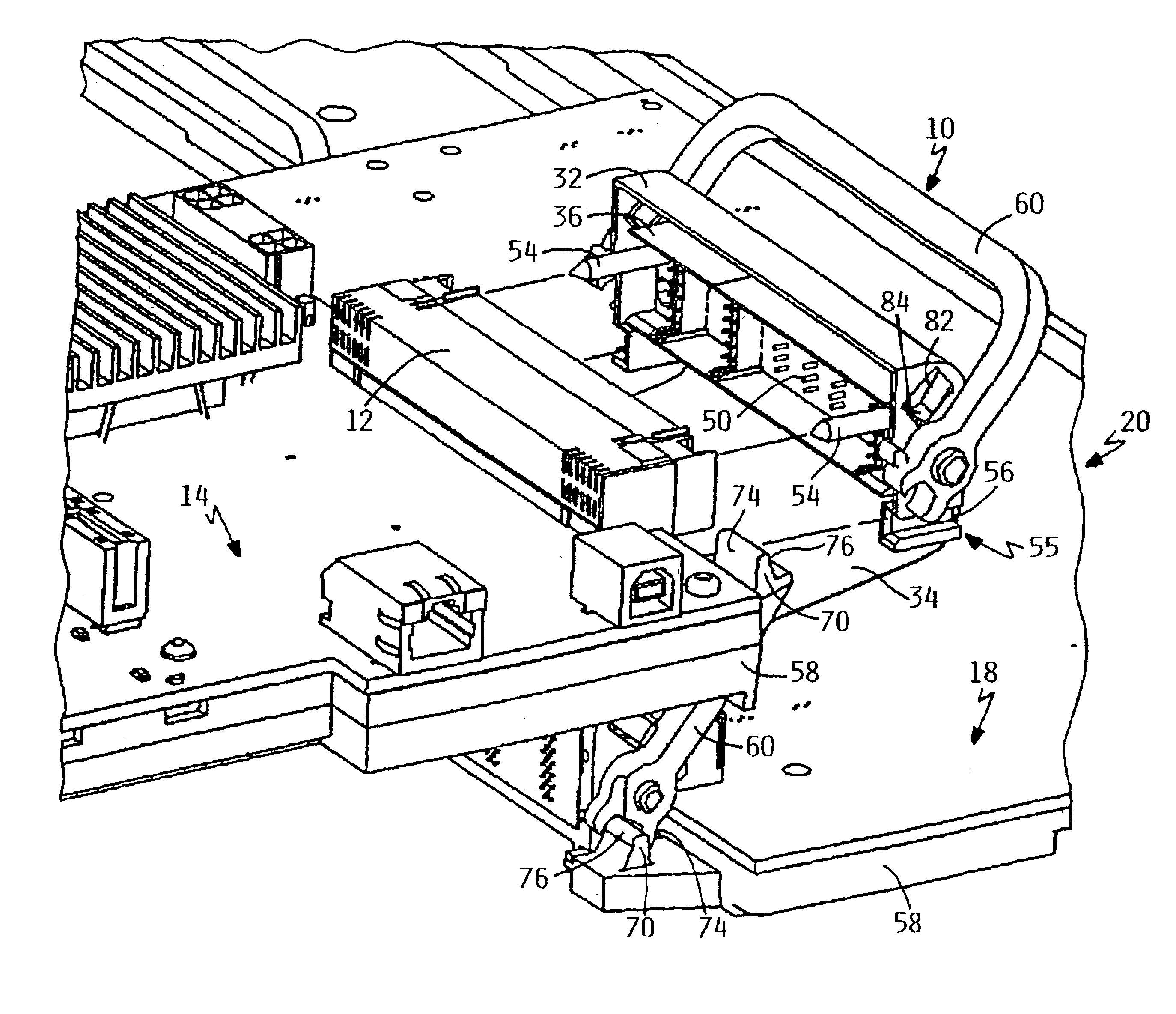
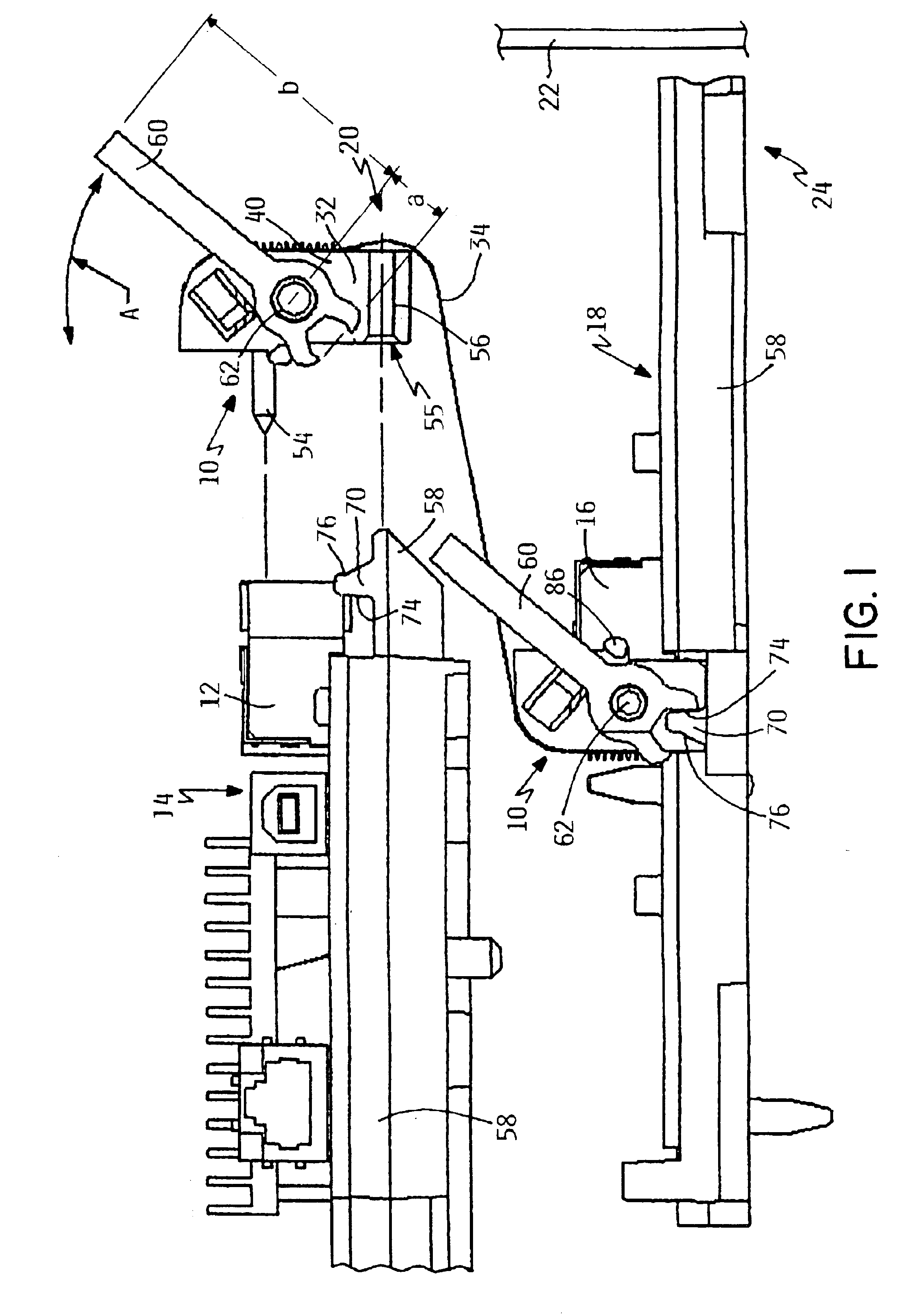
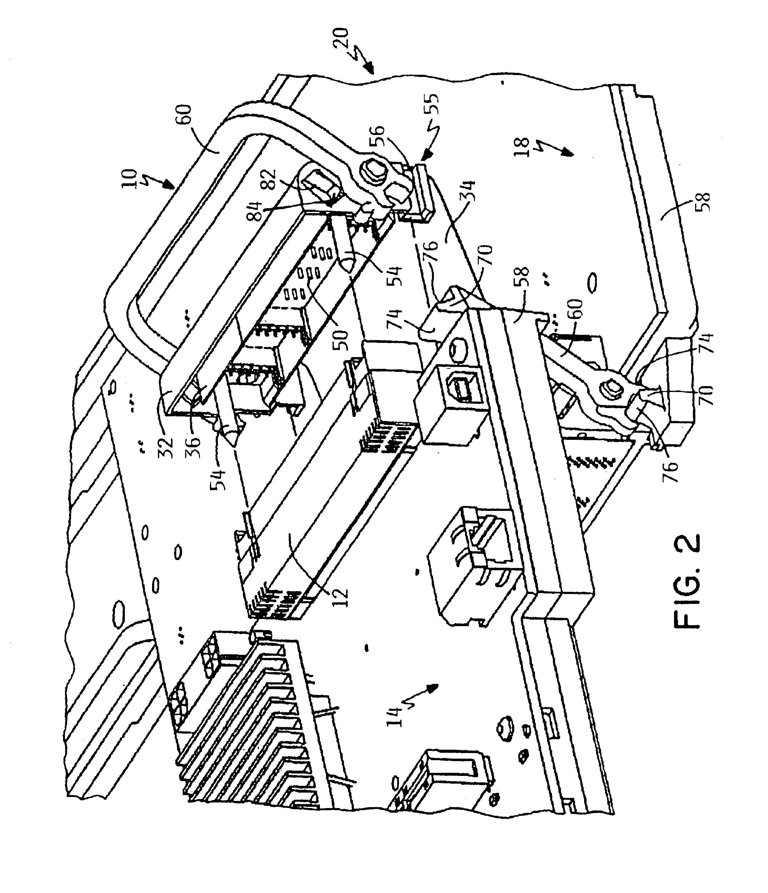
[0023]Reference is made to FIGS. 1-5 for illustrating one preferred embodiment of a connector assembly coupling mechanism or coupling mechanism made according to the present invention and which is generally designated by reference numeral 10. The coupling mechanism 10 is particularly adapted for use in releaseably coupling together an electrical connector assembly 12 on a first circuit board assembly 14 to an electrical connector assembly 16 on a second circuit board assembly 18 for use in a connector assembly coupling system 20. For example, the circuit board assemblies 14, 18 are illustrated as being within a chassis 22, only a portion of which is shown, of a computer system 24. It will be understood that the coupling mechanism 10 can be used in a variety of different environments wherein it is desirable to releaseably retain a cable to and between different electrical connector assemblies.

[0024]In an exemplary embodiment, the coupling mechanism 10 includes a connector assembly ho...


PUM


Abstract

A connector coupling mechanism comprises a housing coupled to a first connector; and, a force applying device connected to the housing and being movable between docking and undocking positions; wherein in response to the force applying device moving to the docking position, a mechanical advantage is provided for facilitating a firm coupling of the first and second connector assemblies. In addition, the force applying device provides a mechanical advantage in response to the force applying device moving to undocking position for facilitating easy unplugging. The coupling mechanism provides a latching arrangement for releasable and positive retention of the force applying device in the docked position for preventing against inadvertent unplugging. A connector assembly coupling system is provided as well as a method of coupling connector assemblies.

Description

BACKGROUND OF THE INVENTION[0001]The present invention relates generally to a coupling mechanism for use in coupling together connector assemblies. More particularly, the present invention relates to an improved coupling mechanism that greatly facilitates docking and undocking with the aid of mechanical advantage as well as positively retaining mated connector assemblies.[0002]Cables typically include an electronic connector assembly at opposing ends that are matable with a corresponding connector assembly associated with electronic devices. Such cable connector assemblies are well known in the connector assembly art and include a universal serial bus (USB)-type connector assembly, a parallel connector assembly, a serial connector assembly, and the like.[0003]Cable connector assembly coupling systems are generally employed to reduce the likelihood that a cable connector assembly will be unintentionally unplugged or decoupled from a connector assembly port; thus insuring continuous e...

Claims


Application Information

Patent Timeline
IPC IPC(8): H01R13/629
CPCH01R13/62933H01R12/7005
Inventor MIKHAIL, AMANDA ELISALANING, RAY CLEMENTMARROQUIN, CHRISTOPHER MICHAELSHURSON, SCOTT ALANSTANCZYK, BRIAN JOSEPH
Owner IBM CORP
Why Eureka
Try Eureka